3D printing building support platform with limiting structure and convenient to assemble

A construction appliance and 3D printing technology, applied in building construction, building material processing, construction, etc., can solve the problems of large support platform, time-consuming and labor-intensive, and unfavorable work efficiency.

Inactive Publication Date: 2020-10-27
福建省泷澄建设集团有限公司
View PDF0 Cites 0 Cited by
  • Summary
  • Abstract
  • Description
  • Claims
  • Application Information

AI Technical Summary

Problems solved by technology

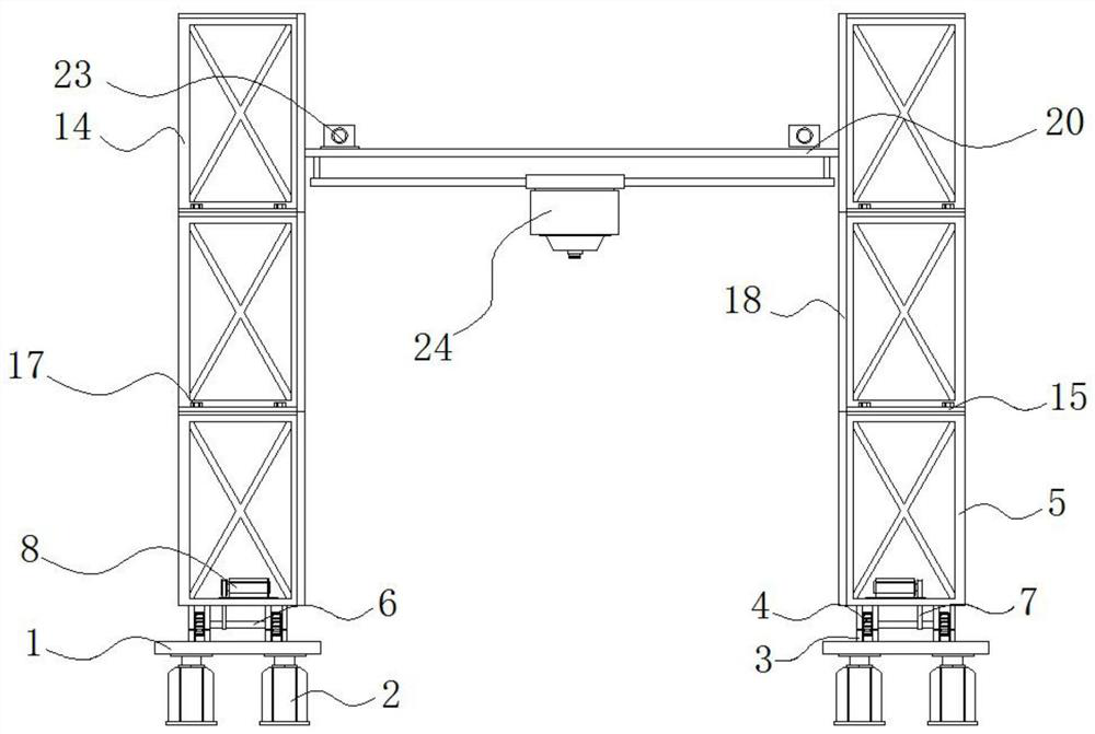
[0004] Aiming at the deficiencies of the prior art, the present invention provides a support platform with a limit structure for easy assembly for 3D printing buildings, which solves the problem that the existing 3D printing equipment needs to set up the support platform in advance when printing the building wall in the above-mentioned background technology It is used to move the printer head, but due to the volume of the building, the support platform is bulky and needs to be assembled. However, the support platform of the current construction 3D printing equipment is troublesome to assemble, the splicing accuracy is not high, it is too time-consuming and laborious, and it is not conducive to improving work efficiency.

Method used


Image

  • 3D printing building support platform with limiting structure and convenient to assemble
  • 3D printing building support platform with limiting structure and convenient to assemble
  • 3D printing building support platform with limiting structure and convenient to assemble

Examples


Embodiment Construction

[0027] The following will clearly and completely describe the technical solutions in the embodiments of the present invention with reference to the accompanying drawings in the embodiments of the present invention. Obviously, the described embodiments are only some, not all, embodiments of the present invention.

[0028] In the description of the present invention, unless otherwise stated, the meaning of "plurality" is two or more; the terms "upper", "lower", "left", "right", "inner", "outer" , "front end", "rear end", "head", "tail", etc. indicate the orientation or positional relationship based on the orientation or positional relationship shown in the drawings, and are only for the convenience of describing the present invention and simplifying the description, rather than Nothing indicating or implying that a referenced device or element must have a particular orientation, be constructed, and operate in a particular orientation should therefore not be construed as limiting ...


PUM


Abstract

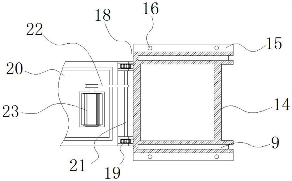
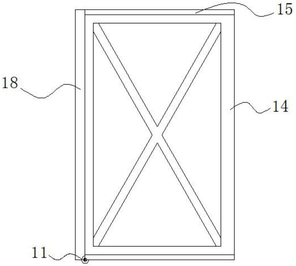
The invention discloses a 3D printing building support platform with a limiting structure and convenient to assemble, and relates to the technical field of 3D printing building support platforms. The3D printing building support platform specifically comprises an adjustable bottom plate, climbing rollers and heightening supports, wherein jacks are fixed to the two ends of the bottom of the adjustable bottom plate; sliding wheels are arranged in sliding rails; the inner sides of the sliding wheels are connected with first rotating shafts; the climbing rollers are arranged in sliding grooves; the two ends of springs are connected with limiting columns; the heightening supports are connected to the tops of the climbing rollers; and threaded holes are formed in the surface of a connecting platform. According to the 3D printing building support platform with the limiting structure and convenient to assemble, the heightening supports slide along the interiors of the sliding grooves through the climbing rollers till the heightening supports slide to the tops of sliding bases, then clamping bolts penetrate the threaded holes to be screwed, and assembling can be finished. The assembling manner is convenient to operate, splicing is simple, the splicing precision is high, the time needed for assembling can be better shortened, and the labor burden of workers can be better relieved.

Description

technical field [0001] The invention relates to the technical field of 3D printing building support platforms, in particular to a 3D printing building support platform with a limiting structure for easy assembly. Background technique [0002] As 3D printing technology is becoming more and more perfect, not only small items can be printed, but this technology can even revolutionize the traditional construction industry. It works basically the same as ordinary printers, which are filled with bondable materials such as powdered metal or plastic. After being connected to the computer, the blueprint on the computer is finally turned into a real object through layer after layer of multi-layer printing. This technology is now applied in many fields, and people use it to make clothing, buildings, cars, etc. . [0003] Existing 3D printing equipment needs to set up a support platform in advance for the movement of the printer head when printing the building wall. However, due to the...

Claims


Application Information

Patent Timeline
IPC IPC(8): E04G21/04B33Y30/00
CPCB33Y30/00E04G21/0427
Inventor 曾精威林鹭军张党生黄树军
Owner 福建省泷澄建设集团有限公司
Why Eureka
Try Eureka