Drainage system for overmining area of coal mine

A drainage system and mining area technology, applied in drainage, mining equipment, earth square drilling and mining, etc., can solve problems such as blockage, drainage effects, and inability to handle soil residues well

Inactive Publication Date: 2020-10-27
惠安县崇武镇栓锋广告设计中心
View PDF6 Cites 1 Cited by
  • Summary
  • Abstract
  • Description
  • Claims
  • Application Information

AI Technical Summary

Problems solved by technology

[0004] The purpose of the present invention is to solve the shortcomings that the existing drainage device can not handle the soil residue well, which is easy to cause blockage during drainage, and has a great impact on the drainage effect, and proposes a drainage system for over-mining areas of coal mines

Method used


Image

  • Drainage system for overmining area of coal mine
  • Drainage system for overmining area of coal mine
  • Drainage system for overmining area of coal mine

Examples


Embodiment 1

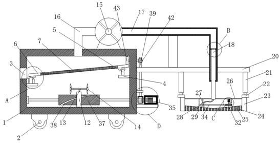
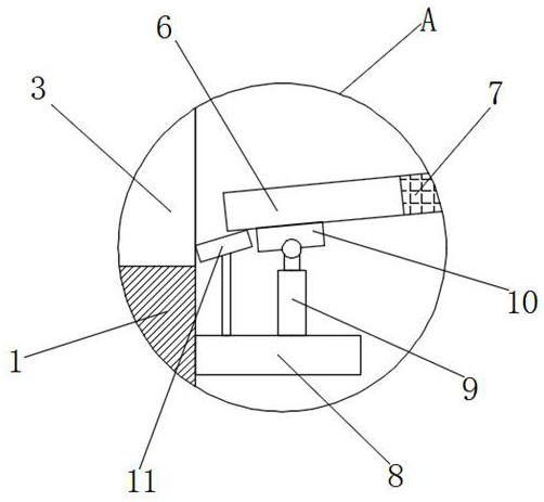
[0029] refer to Figure 1-6 , a drainage system for a coal mine overexploitation area, including a box body 1, a plurality of bottom wheels 2 are symmetrically fixedly installed on the bottom of the box body 1, to facilitate the movement of the whole device, and a filter residue port 3 is opened on one side of the box body 1, and the box body 1 A baffle 6 is movable installed in the body 1, and a filter screen 7 is fixedly installed on the baffle 6, which can effectively separate the pumped mud residue. A first fixed plate 8 is fixedly installed on the inner wall of one side of the first fixed plate 8, and the bottom end of the telescopic rod 9 is fixedly mounted on the top of the first fixed plate 8, and the top end of the telescopic rod 9 is movably installed on the bottom of the first connecting plate 10, and the first fixed plate 8 The top of the plate 8 is fixedly equipped with a slant plate 11, and a first support plate 12 is slidably installed on the bottom inner wall o...

Embodiment 2

[0040] refer to Figure 1-6 , a drainage system in a coal mine overexploitation area, including a box body 1, the bottom of the box body 1 is symmetrically fixed with several bottom wheels 2 by welding to facilitate the movement of the whole device, and a filter residue port 3 is opened on one side of the box body 1 A baffle plate 6 is movable installed in the box body 1, and a filter screen 7 is fixedly installed on the baffle plate 6 by welding, which can effectively separate the pumped mud residue, and the bottom of the baffle plate 6 is slidingly installed with a first connecting plate 10 A first fixed plate 8 is fixedly installed by welding on one side inner wall of the box body 1, and the bottom end of the telescopic rod 9 is fixedly installed on the top of the first fixed plate 8 by welding, and the top end of the telescopic rod 9 is movably installed on the first connection. The bottom of the plate 10, the top of the first fixed plate 8 is fixedly installed with a slan...


PUM


Abstract

The invention belongs to the technical field of drainage devices, in particular to a drainage system for an overmining area of a coal mine. The drainage system for the overmining area of the coal mineprovides the following scheme for solving the problems that an existing drainage device cannot well treat soil residues, blockage during drainage is likely to be caused, and the drainage effect is greatly influenced. The drainage system for the overmining area of the coal mine comprises a box body; a plurality of bottom wheels are symmetrically and fixedly mounted at the bottom of the box body, aresidue filtering opening is formed in one side of the box body, a baffle is movably mounted in the box body, a filter screen is fixedly mounted on the baffle, a first connecting plate is slidably mounted at the bottom of the baffle, a first fixing plate is fixedly mounted on the inner wall of one side of the box body, the bottom end of a telescopic rod is fixedly mounted at the top of the firstfixing plate, the top end of the telescopic rod is movably mounted at the bottom of the first connecting plate, and an inclined plate is fixedly mounted at the top of the first fixing plate. The drainage system is convenient to use and move, water and soil can be effectively separated during drainage, residual filter residues are discharged, and the drainage efficiency is guaranteed.

Description

technical field [0001] The invention relates to the technical field of drainage devices, in particular to a drainage system for coal mine overexploitation areas. Background technique [0002] Due to the coal mining process, underground coal resources need to be mined and transported away. Generally, ore and coal are transported in excavated tunnels. The tunnel-type coal mine goaf that will be left after the coal mining operation is completed, due to the tunnel-type The coal mine goaf is in a concave shape, and it is easy to accumulate water inside. After a long time, it will cause ground subsidence and subsidence. The silt in the goaf is washed away and taken away, and the silt taken away is easy to adhere to the inside of the filter hole of the filter screen, which will easily lead to a decrease in the smoothness of the filter hole. In addition, there is usually no bolt-compressed sewage discharge and silt filter structure. It is often impossible to filter the deposited si...

Claims


Application Information

Patent Timeline
Patent Type & Authority Applications(China)
IPC IPC(8): E21F16/00B01D29/01B01D29/96B01D35/02
CPCB01D29/01B01D29/96B01D35/02E21F16/00
Inventor 潘建锋林素妹
Owner 惠安县崇武镇栓锋广告设计中心
Why Eureka
Try Eureka