
Output power speeder of heat energy power engine

A technology of engine output and governor, which is applied to engine components, machines/engines, mechanical equipment, etc., can solve the problems of not particularly stable engine deceleration effect, unfavorable promotion and use of reducers, and decreased device safety protection capabilities.

Pending Publication Date: 2020-10-27
SHAANXI TECHN INST OF DEFENSE IND
View PDF5 Cites 0 Cited by
  • Summary
  • Abstract
  • Description
  • Claims
  • Application Information

AI Technical Summary

Problems solved by technology

[0003] At present, the existing output power governors for thermal power engines are not particularly stable in decelerating the engine due to the particularity of thermal power engines during use, and it is easy to cause idling to cause the reducer to fail, making the device The safety protection ability has declined, which is not conducive to the promotion and use of the reducer

Method used


Image

  • Output power speeder of heat energy power engine
  • Output power speeder of heat energy power engine
  • Output power speeder of heat energy power engine

Examples


Embodiment Construction

[0022] In order to make the above objects, features and advantages of the present invention more comprehensible, specific implementations of the present invention will be described in detail below in conjunction with the accompanying drawings.

[0023] In the following description, a lot of specific details are set forth in order to fully understand the present invention, but the present invention can also be implemented in other ways different from those described here, and those skilled in the art can do it without departing from the meaning of the present invention. Similarly generalized, the present invention is therefore not limited by the specific embodiments disclosed below.

[0024] Secondly, the present invention is described in detail in conjunction with schematic diagrams. When describing the implementation of the present invention in detail, for the convenience of explanation, the cross-sectional view showing the device structure will not be partially enlarged accor...


PUM


Abstract

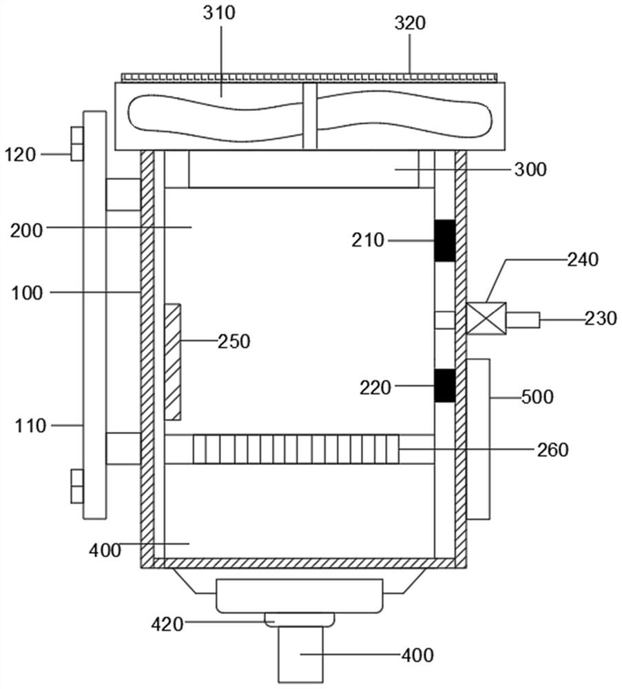
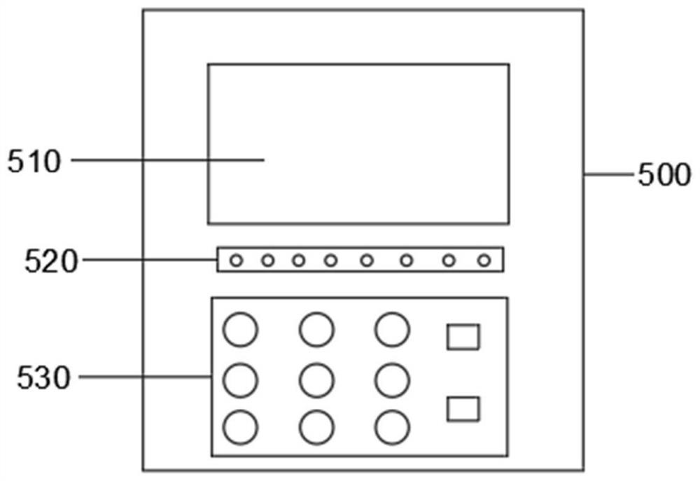
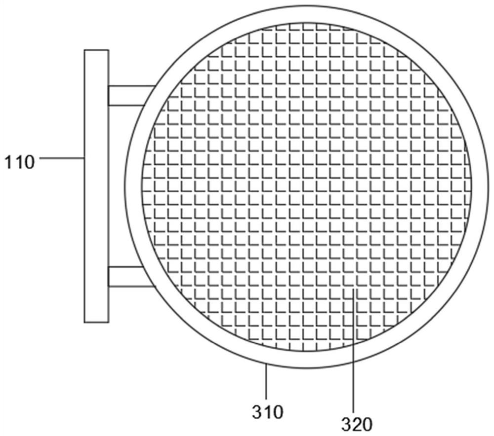
The invention belongs to the technical field of engine speeders, and particularly discloses an output power speeder of a heat energy power engine. The output power speeder comprises a protection shell, a combustion bin, a compressor, an engine body and a control box. The combustion bin is arranged in the middle of an inner cavity of the protection box, and an oil inlet pipe penetrating through theprotection shell is arranged on the right side wall of the combustion bin. A solenoid valve is arranged on the oil inlet pipe, and a pressure sensor is arranged at the top of the right side wall of the combustion bin. The output power speeder is reasonable in structure, and the output power of the engine is detected through a rotating speed sensor; by means of the cooperation of a monitoring terminal, a data transmission module, a processor, a driver and the solenoid valve, the flow of the oil inlet pipe can be controlled conveniently through the solenoid valve, and therefore the output powerof the engine is adjusted; and a temperature sensor and the pressure sensor are arranged in the inner cavity of the combustion bin, the situation that the temperature and pressure in the combustion bin are too high, and consequently cylinder exploding is caused is avoided, and safety performance is improved.

Description

technical field [0001] The invention relates to the technical field of engine governors, in particular to a heat power engine output power governor. Background technique [0002] A heat engine is a power machine that converts heat energy generated by conventional combustion or nuclear fuel reaction, geothermal energy, and solar energy into mechanical work. It is sometimes called a thermodynamic machine, or a heat engine for short. It is the main power machinery utilized by human beings. Commonly used heat engines include internal combustion engines (including gasoline engines, diesel engines, and gas engines, etc.), gas turbines, and steam power plants. They all rely on the intermediate working fluid to complete the thermal power conversion. The heat engine supplies heat to the working fluid by a high-temperature heat source. Take the steam power plant as an example: water in the boiler absorbs the high-temperature heat generated by fuel combustion to become high-temperat...

Claims


Application Information

Patent Timeline
IPC IPC(8): F02C9/28F02C9/26F02C3/04F01D25/24F23R3/42
CPCF01D25/24F02C3/04F02C9/263F02C9/28F23R3/42
Inventor 王飞腾
Owner SHAANXI TECHN INST OF DEFENSE IND
Learn More