
A method for automatic detection of truck brake beam pillar faults

A technology for automatic detection and braking of beams, applied in braking safety systems, instruments, calculations, etc., can solve the problems of missed detection and wrong detection of brake beam pillar faults, and avoid easy missed detection, avoid wrong detection, and identify The effect of high accuracy

Active Publication Date: 2021-03-05
HARBIN KEJIA GENERAL MECHANICAL & ELECTRICAL CO LTD
View PDF7 Cites 0 Cited by
  • Summary
  • Abstract
  • Description
  • Claims
  • Application Information

AI Technical Summary

Problems solved by technology

[0003] The purpose of the present invention is to solve the problem of missed detection and wrong detection of brake beam pillar faults that are prone to occur in manual detection methods, and propose an automatic detection method for truck brake beam pillar faults

Method used


Image

  • A method for automatic detection of truck brake beam pillar faults
  • A method for automatic detection of truck brake beam pillar faults
  • A method for automatic detection of truck brake beam pillar faults

Examples


specific Embodiment approach 1

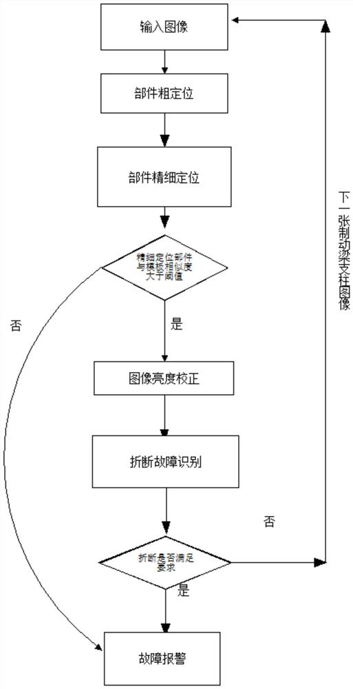
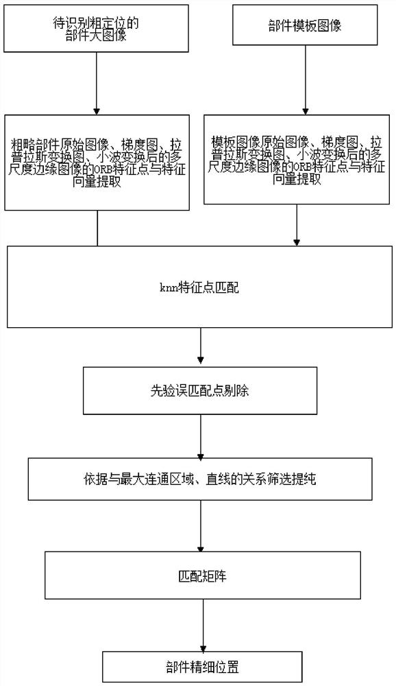
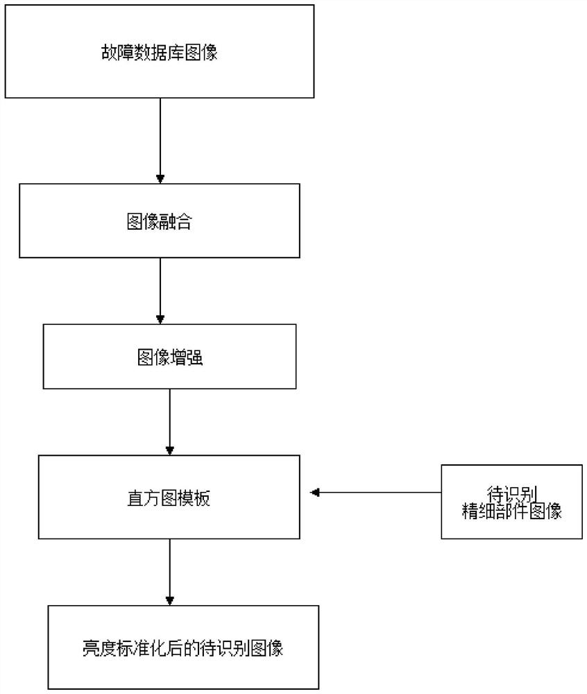
[0023] DETAILED DESCRIPTION One: Combination Figure 1 to 3 This embodiment is described. The method of automatic detection method according to the truck brake beam of the present embodiment, the method specifically includes the steps of:

[0024] Step 1, get the original image containing the brake beam pillar member;

[0025] Step 2, gradient transformation, Laplas transform, and wavelet transform respectively, obtain the original image after the gradient transformation, the original image after the Laplas transform, and the original image after wavelet transform;

[0026] Extract the original image, the original image after the gradient transformation, the original image after Lapus transform, the ORB feature point and feature vector of the original image after wavelet transform, the extracted ORB feature points as the first group of ORB features point;

[0027] Other components of the non-braking beam strut portion easily cause interference to the brake beam struts, and the pres...

specific Embodiment approach 2

[0043] DETAILED DESCRIPTION OF THE INVENTION Different from the specific embodiment of the present embodiment: the specific process of the steps:

[0044] Step one by one, get a truck image;

[0045] Step 12, using the priori knowledge of the wheelbase information and the brake beam strut component position from the step of the truck image to be coarsely positioned out of the position of the brake beam strip member, the coarse positioned sub-map is included as included The original image of the brake beam strut component.

specific Embodiment approach 3

[0046] DETAILED DESCRIPTION OF THE INVENTION The third embodiment is different from that of the particular embodiment: the specific method of acquiring the truck image in the step one by one: the high-definition imaging device is built around the truck track, and the truck is acquired when the truck is passed through a HD imaging device. .


PUM


Abstract

The invention discloses an automatic detection method for a fault of a brake beam pillar of a truck, which belongs to the technical field of fault detection of a brake beam pillar of a truck. The invention solves the problem that the manual detection method is prone to missed detection and wrong detection of the failure of the brake beam pillar. In the present invention, high-definition imaging equipment is respectively built around the track of the truck, and clear images are obtained after the truck passes through the equipment. Roughly locate the brake beam strut components using wheelbase information and prior knowledge of the brake beam strut location. The image of the rough positioning part is further processed to determine whether it is broken. If a break occurs, the recognition result is mapped to the original image according to the mapping relationship, and an alarm is uploaded. The staff will make corresponding processing according to the identification results to ensure the safe operation of the train. The invention can be applied to the fault detection of the brake beam pillar of the truck.

Description

Technical field [0001] The present invention belongs to the technical field of truck brake beam struts, and specifically, a truck brake beam strut method is related to automatic detection method. Background technique [0002] The brake beam pillar is the main accessories of the brake beam. If it is broken, if it is not possible to detect and overhaul, cracks will become larger, causing a dangerous accident that the lower pulley is falling off on the rail, which will cause the vehicle to subversion, take off For major accidents such as lines, the consequences are unimaginable. Brake beam pillars break the fault is a failure of driving safety, in the brake beam struts, existing methods often perform fault detection in manual inspection images. Due to the detection result, the test results will be affected by the subjective factors of the inspector, therefore, it is easy to have problems such as misprovement, error inspection, etc., so that driving safety is used. Inventive content...

Claims


Application Information

Patent Timeline
Patent Type & Authority Patents(China)
IPC IPC(8): G06K9/34G06K9/46G06K9/62B60T17/22
CPCB60T17/22G06V10/443G06V10/267G06V10/50G06V10/751G06F18/251
Inventor 刘丹丹
Owner HARBIN KEJIA GENERAL MECHANICAL & ELECTRICAL CO LTD
Learn More