Energy-saving asynchronous motor with dustproof and heat dissipation functions
An asynchronous motor, energy-saving technology, applied in the direction of electrical components, electromechanical devices, electric components, etc., can solve problems such as complex operation, inability to intercept dust, and affect the heat dissipation function of the motor
- Summary
- Abstract
- Description
- Claims
- Application Information
AI Technical Summary
Problems solved by technology
Method used
Image
Examples
Embodiment 1
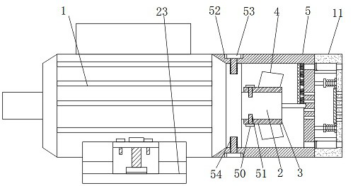
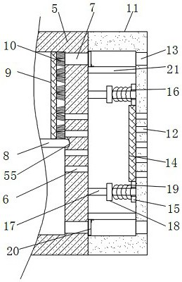
[0038] see Figure 1-10 According to an embodiment of the present invention, an energy-saving asynchronous motor with dust-proof and heat-dissipating functions includes an asynchronous motor body 1, the outer surface of the output shaft 2 at the tail end of the asynchronous motor body 1 is covered with a connecting sleeve 3, and the output The shaft 2 is connected to the connecting sleeve 3 through the connecting mechanism 1, the outer surface of the connecting sleeve 3 is fixedly connected to the fan blade 4, and the tail end of the asynchronous motor body 1 is connected to the casing 5 through the connecting mechanism 2, and the casing 5 A plurality of through holes 6 are opened in the middle of the side away from the asynchronous motor body 1, and through holes 2 7 are opened on the periphery of the through holes 1 6, and the through holes 2 7 are evenly distributed on the surface of the casing 5 ;
[0039] The middle part of the output shaft 2 is fixedly connected with a ...
Embodiment 2
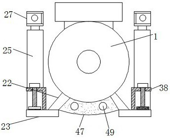
[0045] see Figure 7-9 , the movable mechanism includes a cavity 32, a movable plate 33, a slider 34, a chute 35 and a limit block 36, a cavity 32 is opened inside the top of the L-shaped plate 25, and a cavity 32 is provided inside the cavity 32. Movable plate 33, the top of described movable plate 33 is connected with described U-shaped plate 27, and the both sides of described cavity 32 have chute 35, and the inside of described chute 35 is provided with slide block 34, and described chute 35 The block 34 is fixedly connected with the side wall of the movable plate 33, and the top of the chute 35 is fixedly connected with a limiting block 36, and a spring 2 37 is connected between the sliding block 34 and the limiting block 36, and the The second spring 37 is located in the chute 35, and the movable mechanism can realize the movement of the U-shaped plate 27 in the L-shaped plate 25. When the asynchronous motor needs to be hoisted, by extending the movable plate 33 and the ...
Embodiment 3
[0047] see Figure 7 -with Figure 10 , the clamping mechanism includes a support plate three 38, a screw hole one 39, a screw 40, a rotating block 41, a bearing 42 and a splint 43, and the top middle end of the support plate two 23 is fixedly connected with a support plate three 38, and the support plate The shape design of the third 38 is similar to L-shaped, the top of the support plate three 38 has a screw hole one 39, the internal thread of the screw hole one 39 is connected with a screw 40, and the top of the screw 40 is fixedly connected with a rotating block 41, the bottom of the screw 40 is connected to the splint 43 through the bearing 42, and the bottom of the splint 43 is fixedly connected with an anti-skid pad 44, and the clamping mechanism can realize the clamping of the asynchronous motor and the object, so as to achieve the temporary fixation of the asynchronous motor The anti-skid pad 44 can improve the anti-skid property of the bottom of the splint 43, the t...
PUM
 Abstract
Description
Claims
Application Information
 - R&D
- Intellectual Property
- Life Sciences
- Materials
- Tech Scout
- Unparalleled Data Quality
- Higher Quality Content
- 60% Fewer Hallucinations
Browse by: Latest US Patents, China's latest patents, Technical Efficacy Thesaurus, Application Domain, Technology Topic, Popular Technical Reports.
© 2025 PatSnap. All rights reserved.Legal|Privacy policy|Modern Slavery Act Transparency Statement|Sitemap|About US| Contact US: help@patsnap.com


