
Camera internal temperature test and internal temperature and resolving power test system and method

A technology for internal temperature and testing systems, applied in image communication, television, electrical components, etc., can solve the problems of not being able to monitor the corresponding relationship of cameras in real time, the number of points taken is small, and the corresponding relationship of cameras cannot be accurately reflected

Inactive Publication Date: 2020-10-27
重庆市天实精工科技有限公司
View PDF3 Cites 0 Cited by
  • Summary
  • Abstract
  • Description
  • Claims
  • Application Information

AI Technical Summary

Problems solved by technology

[0003] The existing method for detecting the temperature of the camera is: use a multimeter to test the temperature on the surface of the camera. Due to the interference of the external temperature, and the temperature display accuracy of the multimeter is only 1°C, there is a problem that the test accuracy is not high
Since the entire test is manually operated, the corresponding relationship between the temperature of the camera and the MTF value cannot be monitored in real time. The number of points corresponding to the real-time temperature and MTF value in the entire test is small, and the action between the observed temperature and the observed MTF value of each point will be slow. There is a time interval of at least 1s, so it cannot accurately reflect the correspondence between the internal temperature of the camera and the MTF value of the camera

Method used


Image

  • Camera internal temperature test and internal temperature and resolving power test system and method
  • Camera internal temperature test and internal temperature and resolving power test system and method
  • Camera internal temperature test and internal temperature and resolving power test system and method

Examples


Embodiment Construction

[0037] This embodiment will be described in detail below in conjunction with the accompanying drawings.

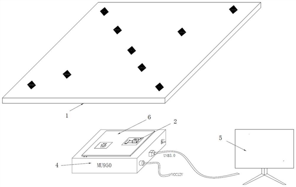
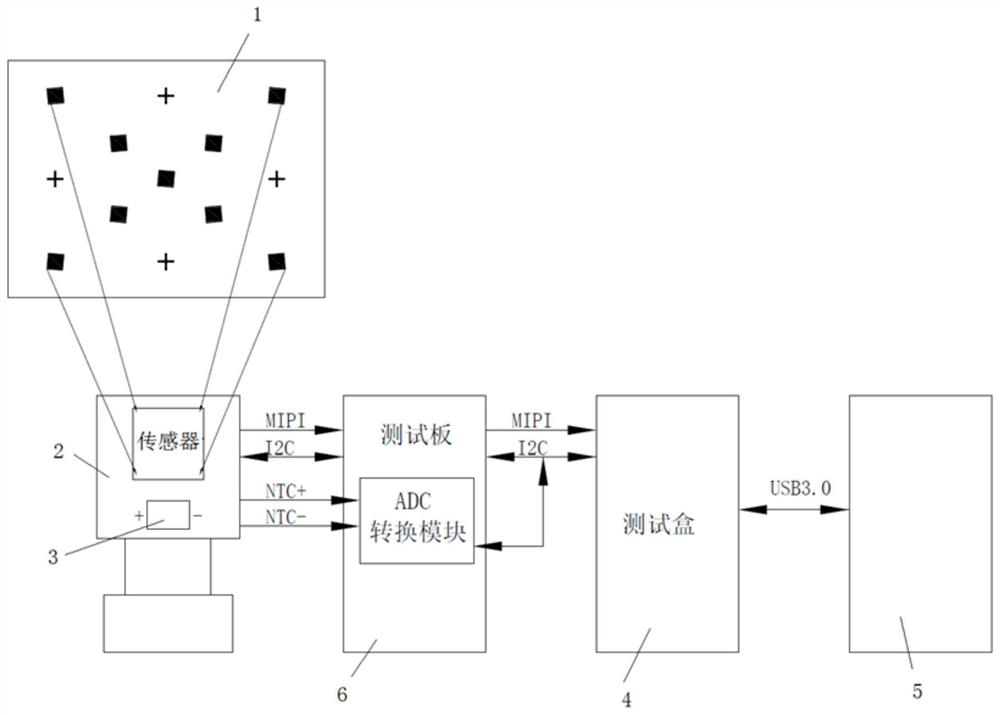
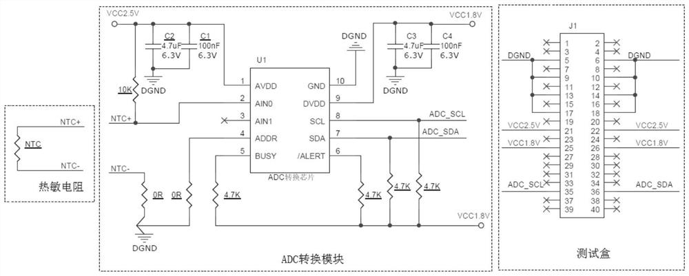
[0038] Such as Figure 1 to Figure 3 As shown, in this embodiment, a camera internal temperature and resolution test system includes a resolution test chart 1 , a thermistor 3 , a test box 4 , a test board 6 and a computer 5 . The resolution test chart 1 is installed in a test light box for providing an MTF test environment. The thermistor 3 is arranged in the camera under test 2 for real-time monitoring of the temperature inside the camera under test. Described test board 6 comprises PCB board, and is arranged on the ADC conversion module on PCB board, and described test board 6 is electrically connected with tested camera 2 and thermistor 3 respectively; Described tested camera 2 is used for shooting MTF test Environment, and the pictures taken are sent to the test box 4 through the test board 6, and the test box 4 obtains the real-time MTF resolution of the camera 2 u...


PUM


Abstract

The invention discloses a camera internal temperature test and internal temperature and resolving power test system and method. The system comprises a resolving power test drawing card, a thermistor,a test box, a test board and a computer. The resolving power test drawing card is installed in the test light box. The thermistor is arranged in a tested camera; the tested camera is used for shootingan MTF test environment and sending a shot picture to the test box through the test board, and the test box obtains the real-time MTF resolving power of the tested camera based on the shot picture; the test board is used for acquiring a voltage value of the thermistor in real time, calculating a real-time resistance value of the thermistor based on the voltage value and sending the real-time resistance value to the test box; the test box is used for sending the real-time MTF resolving power and the real-time resistance value to the computer; and the computer outputs a curve graph corresponding to the temperature and the MTF value. According to the invention, the internal temperature and the MTF value of the camera can be accurately detected in real time, and a curve graph corresponding tothe temperature and the MTF value is output.

Description

technical field [0001] The invention relates to the technical field of camera module testing, in particular to a camera internal temperature test, internal temperature and resolution test system and method. Background technique [0002] Cameras are being updated day by day, high-end pixel cameras have become the mainstream and TOF cameras are added. The high power consumption of high-pixel chips and TOF chips will cause the temperature of the camera to rise significantly during operation, making the technical requirements of camera manufacturers more stringent. Grasp the corresponding relationship between the temperature and the camera, you can understand the stability of the camera. [0003] The existing method for detecting the temperature of the camera is: use a multimeter to test the temperature on the surface of the camera. Due to the interference of the external temperature, and the temperature display accuracy of the multimeter is only 1°C, there is a problem of low t...

Claims


Application Information

Patent Timeline
IPC IPC(8): H04N17/00
CPCH04N17/002
Inventor 黄元乔卢江邓小光齐书晏政波赵军汪科
Owner 重庆市天实精工科技有限公司
Learn More