Production method for pressed components, press molding device, and metal plate for press molding

A manufacturing method and technology of stamping forming, applied in the field of stamping parts manufacturing, can solve the problems of limited application range of stamping forming and large cross-section changes

Active Publication Date: 2020-10-27
JFE STEEL CORP
View PDF7 Cites 0 Cited by
  • Summary
  • Abstract
  • Description
  • Claims
  • Application Information

AI Technical Summary

Problems solved by technology

[0007] However, in Patent Document 1, it is necessary to provide a step shape in the vertical wall portion, so the cross-sec

Method used


Image

  • Production method for pressed components, press molding device, and metal plate for press molding
  • Production method for pressed components, press molding device, and metal plate for press molding
  • Production method for pressed components, press molding device, and metal plate for press molding

Examples


Embodiment

[0094] Next, examples of this embodiment will be described.

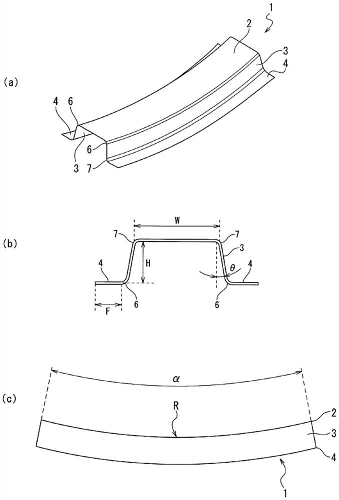
[0095] It is assumed that it is a 1180MPa grade cold-rolled steel plate (thickness 1.4mm), for such figure 1 The press forming of a member having a shape as shown will be analyzed.

[0096] In this embodiment, shape parameters defining the part shape 1 are set as follows.

[0097]

[0098] Top plate width W: 100mm

[0099] Vertical wall height H: 50mm

[0100] Vertical wall angle θ: 10 degrees

[0101] Flange length f: 30mm

[0102]

[0103] Bending angle α: 30 degrees

[0104] Roof curvature radius R: 1000mm

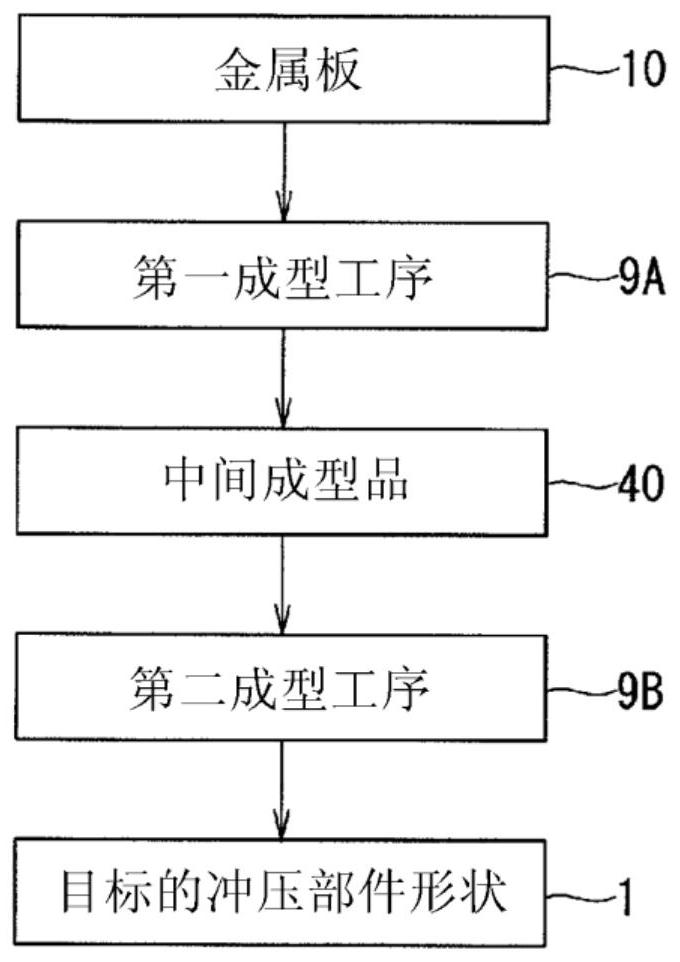
[0105] The metal plate 10 used for forming is set so that the length in the longitudinal direction is equal to the length in the longitudinal direction of the top plate portion 2 of the target punched part shape 1 . Specifically, the length in the longitudinal direction of the metal plate 10 was set to 523.6 mm based on the above-mentioned (1) formula. In addition, the width is set to approximatel...


PUM

PropertyMeasurementUnit
Tensile strengthaaaaaaaaaa

Abstract

Provided is a press molding technology capable of reducing molding defects in molded components having a hat-shaped cross section having a shape bent so as to curve outwards on a flange section side,in the side view. This production method has a first molding step (9A) in which a metal plate (10) is press-molded on to an intermediate molded article (40) and a second molding step (9B) in which theintermediate molded article (40) is bent, said intermediate molded article (40) having a wave shape that: has undulations that continue in the longitudinal direction thereof, at a vertical wall-forming position (13) and a flange section-forming position (14); and has an increasing amplitude in the plate thickness direction of the undulating shape, increasing towards to a position corresponding tothe boundary between the vertical wall section (3) and the flange section (4). The length of the longitudinal direction at a position corresponding to the boundary between the vertical wall section (3) and the flange section (4) in the intermediate molded article (40) is equal to or close to the length of the longitudinal direction of the boundary between the vertical wall section (3) and the flange section (4) in the press-molded shape (1).

Description

technical field [0001] The present invention relates to a technique for manufacturing a hat-shaped cross-sectional stamped part having one or more bent portions protruding toward the flange portion side (recessed toward the top plate portion side) along the longitudinal direction when viewed from the side. The present invention is particularly applicable to the manufacture of an automobile frame member having a portion bent toward the top plate side when viewed from the side. Background technique [0002] The automobile frame member has, for example, a top plate, vertical wall portions continuous in the left and right width directions of the top plate, and a flange portion, and has a shape having a curved portion curved in the longitudinal direction when viewed from the side. When such an automobile frame member is manufactured by press forming from a flat metal plate, a part of the member may be cracked or wrinkled, resulting in poor molding. In addition, there is a concer...

Claims


Application Information

Patent Timeline
IPC IPC(8): B21D22/26B21D19/08B21D22/02B21D22/20B21D24/00
CPCB21D22/02B21D22/20B21D53/88B21D19/08B21D22/26B21D24/00
Inventor 三宅弘人新宫丰久山崎雄司
Owner JFE STEEL CORP
Why Eureka
Try Eureka