Maxillofacial region postoperative drainage system

A facial and communication technology, applied in the extraction and pumping system, suction devices, hypodermic injection devices, etc., can solve the problems of destroying the stability of the syringe, hindering the early movement of patients, and poor fixation

Pending Publication Date: 2020-10-30
中国人民解放军海军军医大学第一附属医院
View PDF17 Cites 0 Cited by
  • Summary
  • Abstract
  • Description
  • Claims
  • Application Information

AI Technical Summary

Problems solved by technology

However, the method of fixing the negative pressure drainage device mentioned above has poor fixability, which will destroy the stability of the needle cylinder, easily cause the needle cylinder to slip, and cannot guarantee safety.
[0004] The common wa

Method used


Image

  • Maxillofacial region postoperative drainage system
  • Maxillofacial region postoperative drainage system
  • Maxillofacial region postoperative drainage system

Examples


Embodiment 1

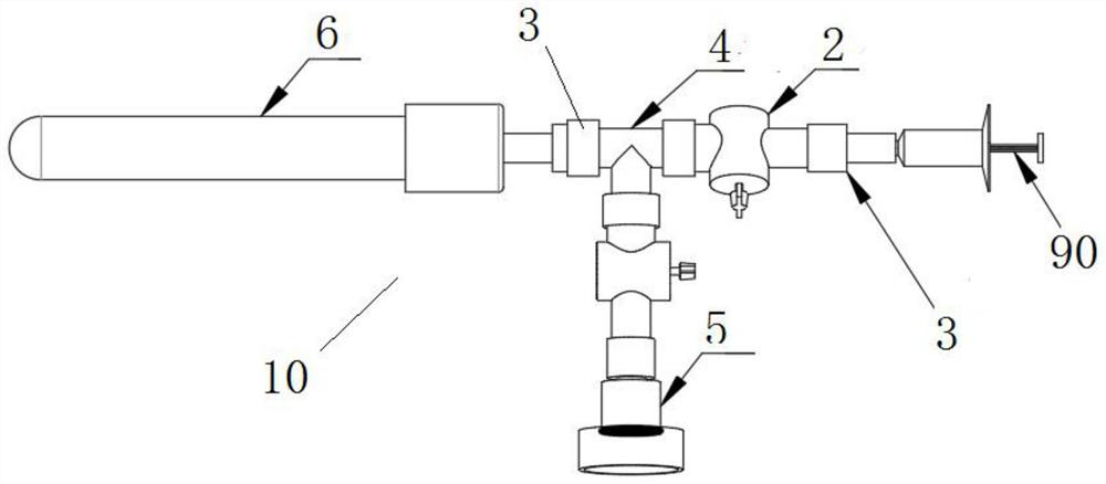
[0031] The drainage system after maxillofacial surgery includes a drainage unit 10 and a first control unit.

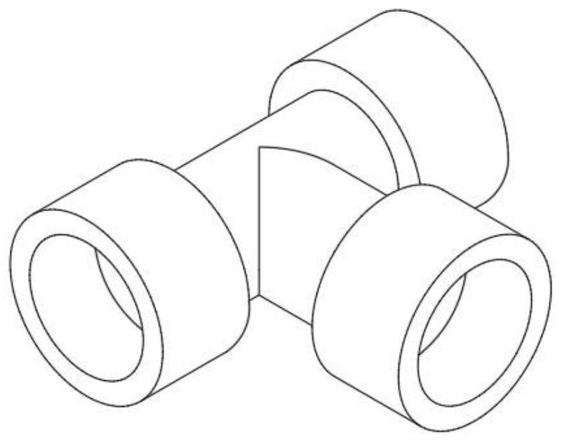
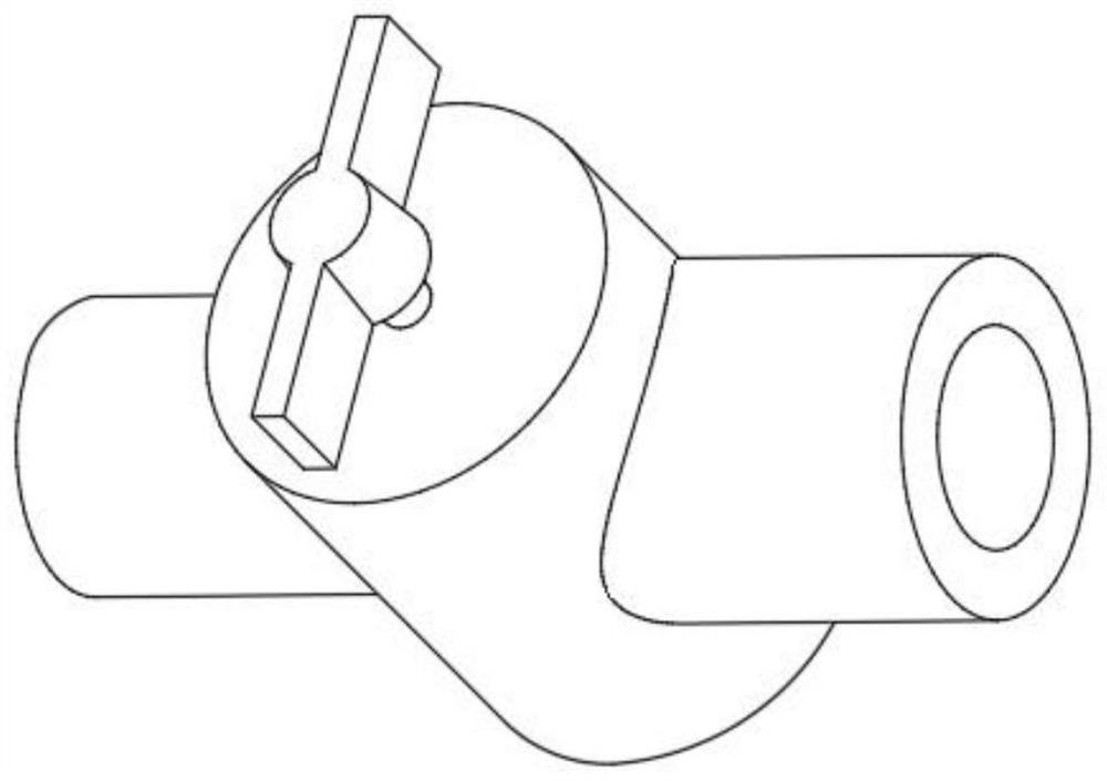
[0032] Such as figure 1 As shown, the drainage unit 10 includes a drainage tube, a control valve 2, a three-way quick connector 4, and a negative pressure bottle 6, wherein, in the drainage tube, such as image 3 shown between the control valve 2 and as figure 2 The three-way quick connector 4 shown, such as Figure 4 The shown negative pressure bottles 6 are respectively connected by connecting hoses 3 .

[0033] One end of the drainage tube communicates with the control valve 2, and the other end is arranged at the drainage site of the patient who needs drainage. The drainage tube, the control valve 2, the three-way quick connector 4, and the negative pressure bottle 6 are connected.

[0034] The first control unit includes a negative pressure regulator and a pressure gauge 5 .

[0035] In an embodiment, the negative pressure regulator is a syringe 90 .

[003...

Embodiment 2

[0042] A drainage system after maxillofacial surgery includes a drainage device and a mobile terminal. The drainage device is connected to the mobile terminal in communication, and the communication connection includes a wired connection and a wireless connection.

[0043] In the embodiment, Bluetooth connection among wireless connections is adopted.

[0044] The drainage device includes a drainage unit 20 and a second control unit.

[0045] Such as Figure 5 As shown, the drainage unit 20 includes a drainage tube, a control valve 2, a three-way quick connector 4, and a negative pressure bottle 6, wherein, between the drainage tube, the control valve 2 and between the three-way quick connector 4 and the negative pressure bottle 6 The connection is made via the connection hose 3.

[0046] One end of the drainage tube communicates with the control valve 2, and the other end is arranged at the drainage site of the patient who needs drainage. The drainage tube, the control valve...

Embodiment 3

[0063] Such as Image 6 As shown, the drainage system after maxillofacial surgery includes a drainage unit 30 and a third control unit.

[0064] The drainage unit 30 includes a drainage tube 1, a control valve 2, and a negative pressure bottle 6 that are connected and communicated in sequence, wherein the connecting hoses are respectively connected between the drainage tube 1, the control valve 2 and between the control valve 2 and the negative pressure bottle 6. 3 Make the connection.

[0065] One end of the drainage tube 1 communicates with the control valve 2, and the other end is set at the drainage site of the patient who needs to be drained, and the purpose of drainage can be achieved by opening the control valve 2.

[0066] The 3rd control unit comprises negative pressure regulator, and in the embodiment, negative pressure regulator is syringe 90, uses syringe 90 to regulate the negative pressure in the bottle of negative pressure bottle 4 (uses syringe 90 to draw outw...


PUM


Abstract

The invention discloses a maxillofacial region postoperative drainage system. The system comprises a drainage device and a mobile terminal. The drainage device comprises a drainage unit and a controlunit. The drainage unit comprises a drainage tube, a control valve, a three-way quick connector and a negative pressure bottle which are sequentially communicated; the control unit comprises a negative pressure adjusting piece, a pressure measurer and a wireless transmitting module. The pressure measurer is used for obtaining a pressure signal; the wireless transmitting module is used for transmitting the pressure signal to the mobile terminal; the mobile terminal comprises a communication part, a control part and a processing part. The control part is at least used for controlling the pressure measurer to measure; the wireless transmitting module is used for transmitting a pressure signal; the communication part receives a pressure signal from the drainage device, the processing part is used for processing and converting the pressure signal into a numerical value or an image and displaying the numerical value or the image on the mobile terminal, the negative pressure adjusting piece adjusts the negative pressure in the negative pressure bottle to determine the optimal negative pressure suction value, and the drainage tube pumps out hydrops of a patient through the negative pressure.

Description

technical field [0001] The invention belongs to the field of medical devices, and in particular relates to a drainage system after maxillofacial surgery. Background technique [0002] Existing negative pressure drainage technology often uses negative pressure tubes of uniform specifications for postoperative care of patients. Due to the differences among individual patients, negative pressure tubes of the same specification cannot be fine-tuned among patients. [0003] The existing indwelling negative pressure drainage device is difficult to fix. For example, patients with congenital deformities in children will use adhesive tape, pins or rubber bands to fix the syringe on the patient gown after surgery, while other diseases will choose to fix it on the external dressing of the head and face. However, the above-mentioned method for fixing the negative pressure drainage device has poor fixability, destroys the stability of the needle cylinder fixation, easily causes the need...

Claims


Application Information

Patent Timeline
IPC IPC(8): A61M1/00
CPCA61M1/0023A61M1/74
Inventor 陈梦婕周励陈东辉朱臻颖朱小梅
Owner 中国人民解放军海军军医大学第一附属医院
Why Eureka
Try Eureka