

Glue scraping device for flat piece and with controllable gluing shape
A squeegee device, flat plate technology, applied in the direction of surface coating device, coating, etc., can solve the problems of high cost, long operation time, inconvenient production and operation, achieve consistent thickness and shape, improve controllability, Surface neat effect
Patent Information
- Authority / Receiving Office
- CN · China
- Patent Type
- Applications(China)
- Current Assignee / Owner
- Publication Date
- 2020-10-30
Smart Images
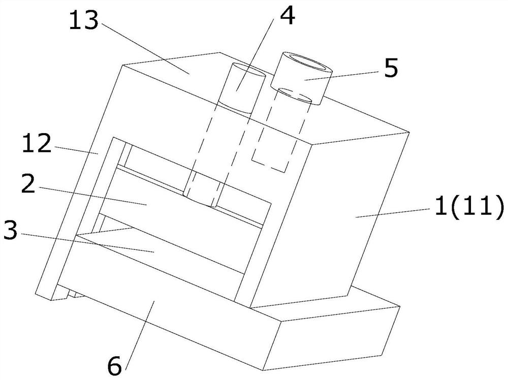
Figure 1 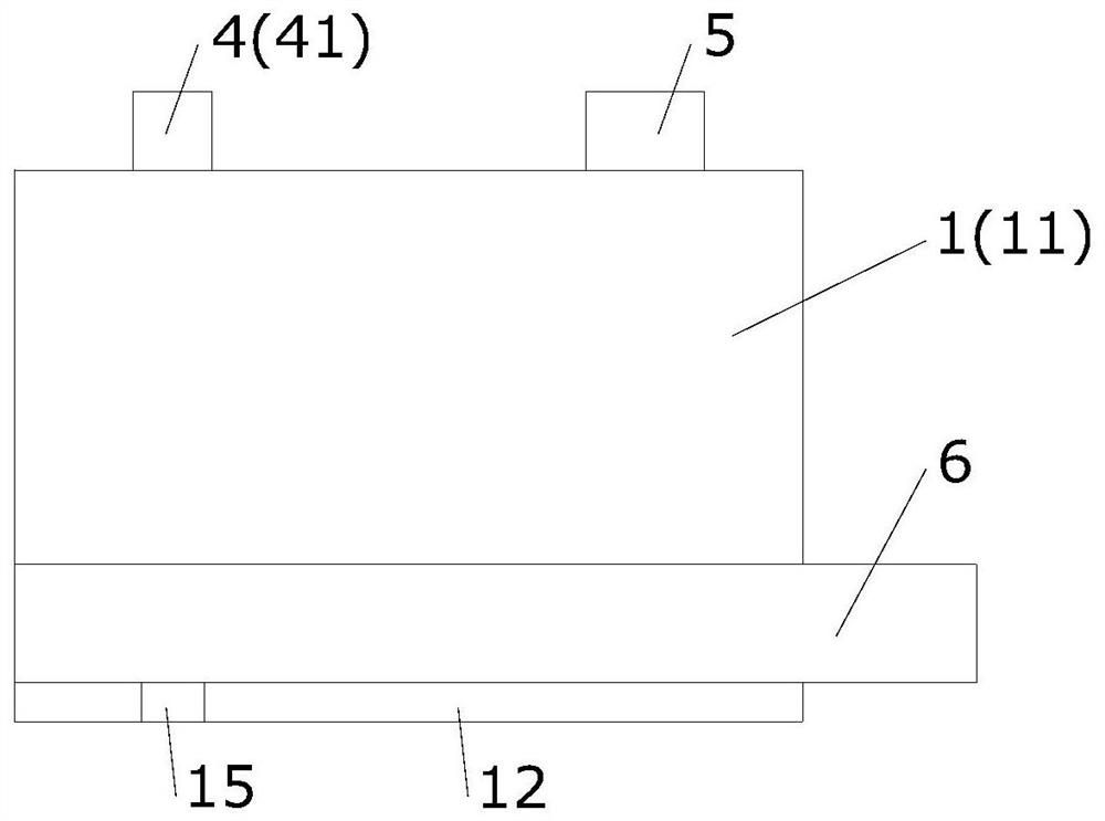
Figure 2 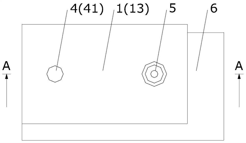
Figure 3
Abstract
Description
technical field
[0001] The invention relates to a squeegee device, in particular to a squeegee device for gluing flat parts. Background technique
[0002] In the manufacture of aircraft interior parts, there are many metal parts hemming or non-metal parts bonding, and the flat structure interior parts account for a large proportion, such as lockers, kitchen and bathroom, door panels, compartment panels, etc. Metal parts or non-metal parts that are consistent with the outline of the composite parts are bonded to the composite parts. In order to ensure the bonding strength and the overall appearance of the interior parts, the manufacturing requirements need to control the thickness of the adhesive layer to achieve a relatively high interior. Part quality requirements.
[0003] Due to the complex shape, large structure and variable bonding position of aircraft interior parts, the automatic squeegee equipment currently on the market is expensive and bulky, which is not convenie...
Examples
Embodiment Construction
[0020] The present invention will be further explained below in conjunction with the accompanying drawings and specific embodiments. These examples are only for illustrating the present invention and are not intended to limit the scope of the present invention.
[0021] A squeegee device with controllable gluing form for flat parts, as attached Figure 1~6 As shown, it includes a U-shaped base 1, a rubber scraper 2, a lifting mechanism 4, and a glue injection adapter 5.
[0022] The U-shaped base 1 is inverted, the opening is downward, and the lower edges of the vertical walls on both sides have a height difference, forming a short vertical wall 11 and a long vertical wall 12. The top wall 13 is provided with a glue injection hole 14, and the glue injection adapter 5 passes through it. The glue injection hole 14 is provided to connect with the top wall 13 .
[0023] The elevating mechanism 4 is a guide post 41, and the guide post 41 penetrates the top wall 13, and the two ar...