Environment-friendly punching and drilling equipment
A kind of punching equipment and environment-friendly technology, applied in the direction of metal processing equipment, feeding device, positioning device, etc., can solve the problems of high cost and complex structure
- Summary
- Abstract
- Description
- Claims
- Application Information
AI Technical Summary
Problems solved by technology
Method used
Image

Examples
Embodiment 1
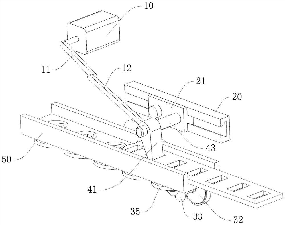
[0025] Such as Figure 1 to Figure 2 As shown, an environment-friendly punching and punching equipment provided by the embodiment of the present invention includes a punching machine, which is located at the rear end of the material conveying direction, and also includes:
[0026] The base 50 is used to carry materials, and the materials move on the base 50;
[0027] The power mechanism comprises a driving motor 10, a connecting rod 11, a friction driving rod 12, a sliding bracket 20 and a slide block 21. One end of the connecting rod 11 is set on the output end of the driving motor 10, and one end of the friction driving rod 12 is hinged to the connecting rod. The other end of the rod 11 and the other end of the friction drive rod 12 are hinged to the slider 21. The slider 21 is slidably arranged on the sliding bracket 20 and the sliding direction of the slider 21 is parallel to the conveying direction of the material. When the motor rotates , to drive the slider 21 to recip...
Embodiment 2
[0031] When punching, the punching is realized by shearing the material. When shearing, burrs will be formed on the lower surface of the material, requiring additional secondary grinding, resulting in increased labor and low efficiency.
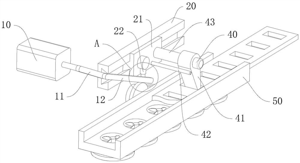
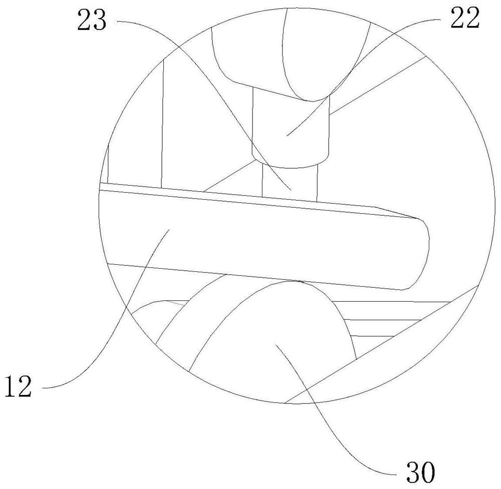
[0032] Such as Figure 3 to Figure 6 As shown, therefore, this embodiment also includes a sliding bar 23, a storage sliding sleeve 22 and a deburring device;
[0033] The storage sliding sleeve 22 is fixedly arranged on the slider 21, and the displacement sliding rod 23 is slidably arranged in the storage sliding sleeve 22; When the rod 23 moves up and down, a space is formed for the friction drive rod 12;
[0034] The deburring device comprises a friction wheel 30, a first pulley 31, a second pulley 32, a first bevel gear 33, a second bevel gear 34, several synchronous wheels 35 and a scraper 36 corresponding to the synchronous wheel 35 one by one; Cooperate with the friction wheel 30, when the friction drive rod 12 is in contact with the...
PUM
 Abstract
Description
Claims
Application Information