Material transferring method for cylinder sleeve machining

A transfer method and cylinder liner technology, applied in metal processing equipment, forming tools, manufacturing tools, etc., can solve the problems of inability to achieve large-scale, intelligent production, time-consuming and labor-intensive, and low degree of automation

Inactive Publication Date: 2020-10-30
ANHUI PROVINCE YUEXI CYLINDER
View PDF0 Cites 4 Cited by
  • Summary
  • Abstract
  • Description
  • Claims
  • Application Information

AI Technical Summary

Problems solved by technology

[0002] After the thin-walled cylinder sleeve blank is processed and formed, one end needs to be flanged to form a sleeve shoulder. Traditional flanging equipment generally uses rigid fixtures to tension the cylinder liner from the inside of the cylinder liner and then rotate the cylinder liner for processing. However, the smoothness of the inner surface of the cylinder liner The requirements are high, and the use of traditional fixtures will easily lead to wear and deformation of the inner wall of the cylinder liner
In addition, in order to protect the surface of the material before flanging the cylinder liner, it is generally necessary to apply oil to the flanging area. Traditional processing methods generally use manual oiling, which is time-consuming and laborious, and affects processing efficiency.
Finally, manual loading and unloading is required for traditional cylinder liner processing, which has a low degree of automation and cannot achieve large-scale and intelligent production

Method used


Image

  • Material transferring method for cylinder sleeve machining
  • Material transferring method for cylinder sleeve machining
  • Material transferring method for cylinder sleeve machining

Examples


Embodiment 1

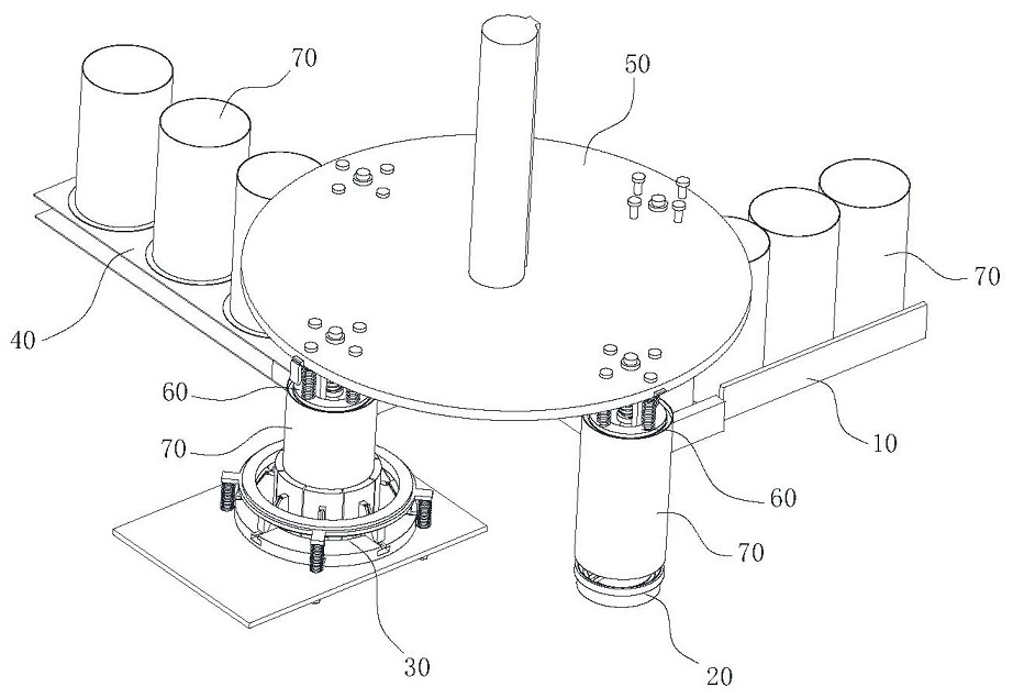
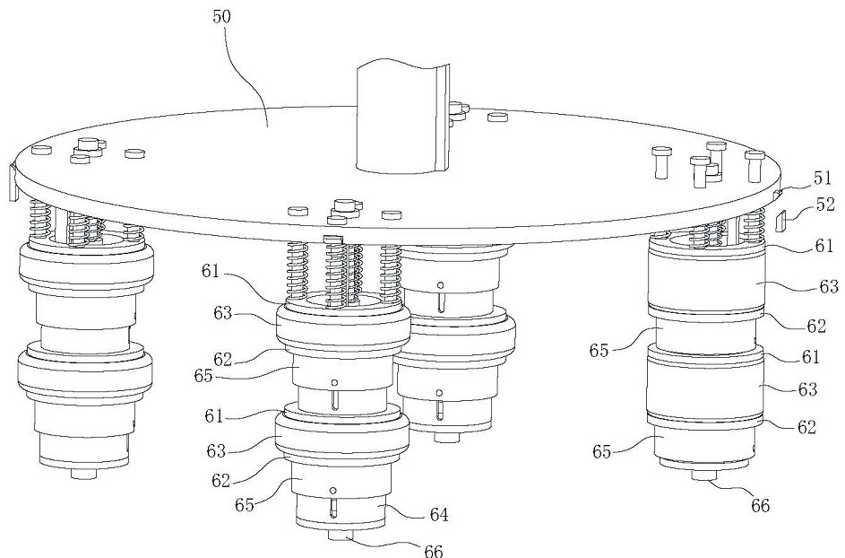
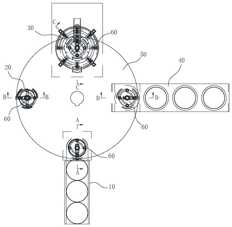
[0030] Such as figure 1 , 3 As shown, a cylinder liner processing system includes a transfer manipulator, and the transfer manipulator includes a circular mounting plate 50. The center of the mounting plate 50 is provided with a rotating shaft. Sliding connection, the frame is provided with a driving element for driving the hand to rotate and slide, the edge of the mounting plate 50 is provided with a clamping unit 60, and the revolving path of the clamping unit 60 is sequentially provided with a reclaiming station and an oiling station , flanging station and unloading station, the reclaiming station is provided with a cylinder sleeve blank conveying trough 10, the oiling station is provided with an oiling device 20, the flanging station is provided with a flanging device 30, and the unloading station The unloading conveyor belt 40 is provided at the station, and the clamping unit 60 clamps the cylinder liner 70 shell blank from the retrieving station, and transfers the cylin...

Embodiment 2

[0039] A method for processing a cylinder liner using the processing system described in Embodiment 1, comprising the steps of:

[0040] Step 1: placing the cylinder liner 70 on the conveying trough 10;

[0041] Step 2: Transfer the barrel blank of the cylinder liner 70 to the oiling station, and oil the inner ring surface of the end of the cylinder liner 70 to be flanged;

[0042] Step 3: transfer the oiled cylinder liner 70 to the flanging station, and perform flanging treatment on the cylinder liner 70;

[0043] Step 4: Transfer the flanged cylinder liner 70 to the unloading station and release the cylinder liner 70 onto the unloading conveyor belt 40 .

Embodiment 3

[0045] A material transfer method for cylinder liner processing, using a manipulator to clamp the cylinder liner 70 from the inside of the cylinder liner 70, and sequentially transfer the cylinder liner 70 through the oiling station, flanging station and unloading station, and The unloading station releases the cylinder liner 70; the manipulator includes a circular mounting plate 50, and the center of the mounting plate 50 is provided with a rotating shaft. There is a drive element for driving the hand to rotate and slide, the edge of the mounting plate 50 is provided with a clamping unit 60, and the revolving path of the clamping unit 60 is sequentially provided with a reclaiming station, an oiling station, and a flanging station and the unloading station, the reclaiming station is provided with a cylinder liner 70 and the barrel conveying trough 10, the oiling station is provided with an oiling device 20, the flanging station is provided with a flanging device 30, and the unl...


PUM


Abstract

The invention belongs to the technical field of engine cylinder sleeve machining, and particularly relates to a material transferring method for cylinder sleeve machining. A manipulator is adopted toclamp a cylinder sleeve from the inside of the cylinder sleeve, the cylinder sleeve is transferred to pass through an oil painting station, a face turning station, and an unloading station successively, and is released on the unloading station, the manipulator includes a circular mounting plate, and clamping units are arranged on the edge of the mounting plate. According to the method, airbag typemanipulator is utilized to achieve the flexible clamping and transferring of the cylinder sleeve, the damage to the inner wall of the cylinder sleeve can be reduced, meanwhile the automatic transferring of the cylinder sleeve between the stations can be achieved, and the production efficiency can be improved.

Description

technical field [0001] The invention belongs to the technical field of engine cylinder liner processing, and in particular relates to a material transfer method for cylinder liner processing. Background technique [0002] After the thin-walled cylinder sleeve blank is processed and formed, one end needs to be flanged to form a sleeve shoulder. Traditional flanging equipment generally uses rigid fixtures to tension the cylinder liner from the inside of the cylinder liner and then rotate the cylinder liner for processing. However, the smoothness of the inner surface of the cylinder liner The requirements are high, and the use of traditional fixtures will easily cause wear and deformation of the inner wall of the cylinder liner. In addition, in order to protect the surface of the material before flanging the cylinder liner, it is generally necessary to apply oil to the flanging area. Traditional processing methods generally use manual oiling, which is time-consuming and laborio...

Claims


Application Information

Patent Timeline
Patent Type & Authority Applications(China)
IPC IPC(8): B21D53/84B21D19/04B21D43/00B21D43/10B21D43/14B21D43/02B21D37/18B25J15/00B25J11/00B05C7/00B05C11/10B05C11/11B05C13/02
CPCB05C7/00B05C11/10B05C11/11B05C13/02B21D19/046B21D37/18B21D43/003B21D43/026B21D43/105B21D43/14B21D53/84B25J11/0075B25J15/0023B25J15/0047
Inventor 周国荣
Owner ANHUI PROVINCE YUEXI CYLINDER
Why Eureka
Try Eureka