A multi-head moving gantry friction stir welding device

A friction stir welding, multi-head technology, applied in welding equipment, non-electric welding equipment, metal processing equipment, etc., can solve the problems of surface oxidation of welding parts, undetectable welding temperature, remote welding parts, etc., and achieve diversified welding performance. , avoid welding defects, reduce the effect of workload

Active Publication Date: 2022-03-15
BEIJING FSW TECH
View PDF9 Cites 0 Cited by
  • Summary
  • Abstract
  • Description
  • Claims
  • Application Information

AI Technical Summary

Problems solved by technology

[0004] Although the existing friction stir welding device has many applications in the field of industrial manufacturing in my country, there are still defects, specifically: 1) If multiple welds are welded at the same time, the welding efficiency can be increased. The existing stirring head has a single function, only It can meet a certain demand, but does not have a variety of friction stir welding needs; 2) When the weldment is fixed on the workbench, the position is inconvenient to adjust, and the fixation is not good, which leads to the remoteness of the weldment during welding, which affects the welding Results; 3) The welding temperature cannot be detected, and the welding route cannot be tracked at the same time, which is prone to welding deviation and reduces the welding effect; 4) When the stirring head is used for stirring welding, if the temperature is too high and needs to be cooled, the cooling method should be the same, and Using a separate cooling method, the cooling effect is not good, and when cooling by cooling water, it is easy to oxidize the surface of the weldment

Method used


Image

  • A multi-head moving gantry friction stir welding device
  • A multi-head moving gantry friction stir welding device
  • A multi-head moving gantry friction stir welding device

Examples


Embodiment Construction

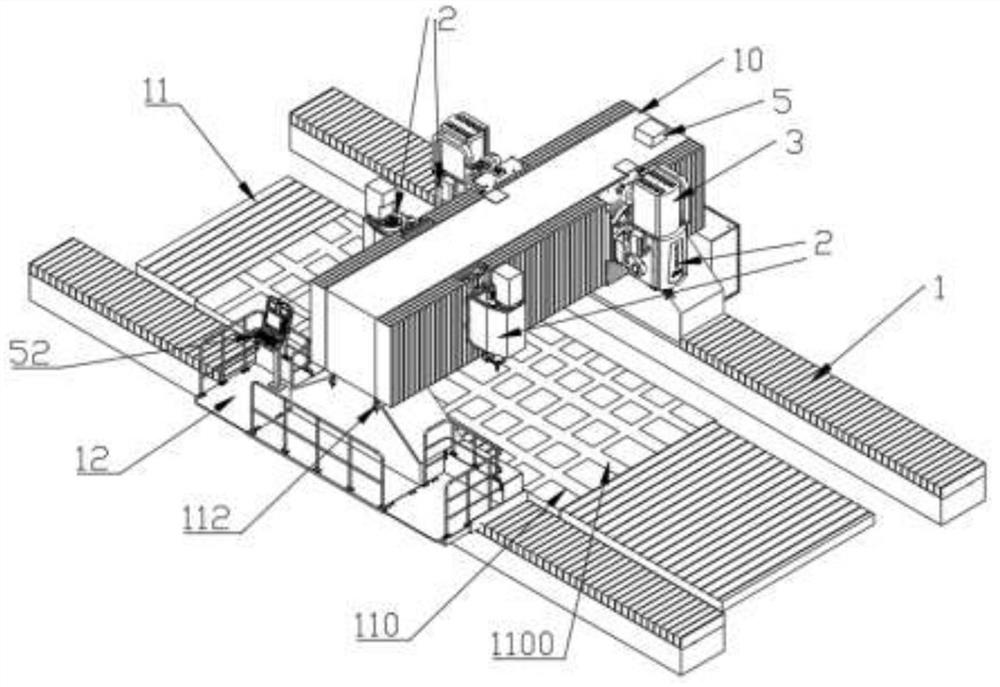
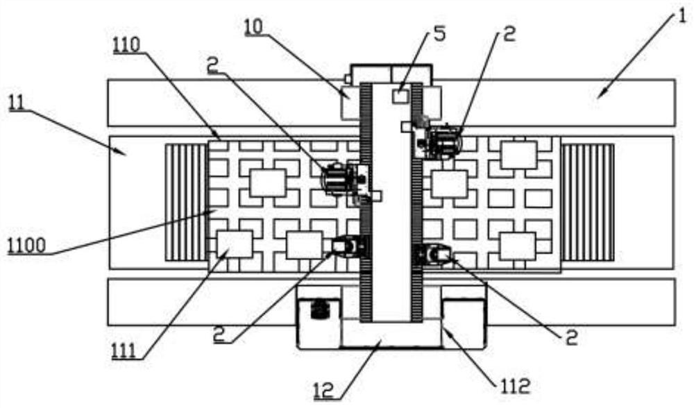
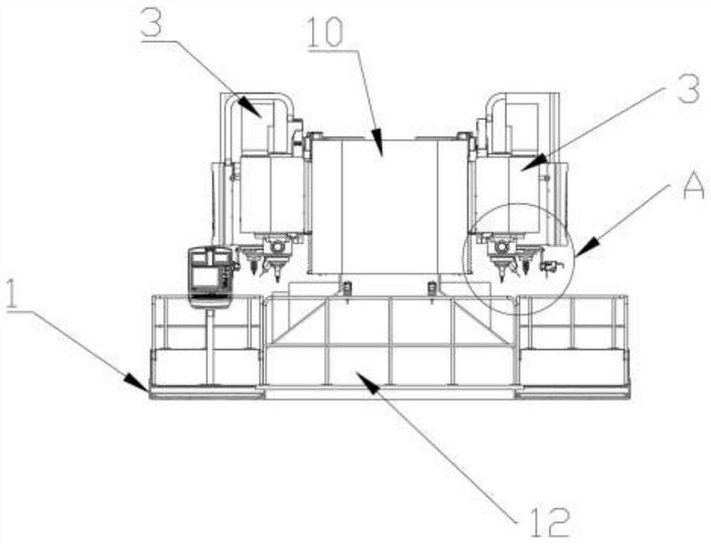
[0036] Example: such as figure 1 , 2 The shown multi-head moving gantry friction stir welding device mainly includes a base 1 arranged on the ground with a gantry 10 on the upper end and a workbench 11 located at the lower end of the gantry 10 along the width direction. Four welding heads 2 of different specifications on the front and rear sides of the beam of the gantry 10 and on the upper end of the workbench 11, the power system 3 that drives each welding head 2 to move, the welding measuring element 4, the intelligent control element 5, and various electrical components the power source to which the component is electrically connected;

[0037] Such as Figure 5 As shown, the workbench 11 is provided with a welding mobile plate 110 that can slide along the width direction of the workbench 11. The upper end of the welding mobile plate 110 is provided with a welding fixture 111 for fixing the weldment, and the upper end of the welding mobile plate 110 is provided with a me...


PUM


Abstract

The invention discloses a multi-head movable gantry friction stir welding device, which belongs to the technical field of friction stir welding equipment. The device mainly includes a base set on the ground with a gantry frame at the upper end and a workbench directly below the gantry frame at the upper end along the width direction, a welding head, a power system, a welding measuring element, an intelligent control element, and various electrical components. The power supply for the electrical connection of the components; the invention integrates multiple friction stir welding welding heads into one bed friction stir welding equipment. This equipment has diversified characteristics and can meet various needs at the same time, and the welding performance is diversified and far superior. Compared with the traditional friction stir welding, it realizes the welding of various complex parts with one equipment; the weldment is adsorbed on the upper ends of multiple T-shaped sliding adsorption blocks through the electromagnetic adsorption plate, and each T-shaped sliding adsorption block is driven by the motor to slide in the positioning sliding groove , so as to complete the automatic adjustment of the position of the weldment, the structure is simple, the operation is convenient, and the workload of the staff is reduced.

Description

technical field [0001] The invention belongs to the technical field of friction stir welding equipment, and in particular relates to a multi-head movable gantry friction stir welding device. Background technique [0002] Friction stir welding is a high-speed rotating stirring head pierced into the workpiece and then moves along the welding direction. Frictional heat is generated at the contact part between the stirring head and the workpiece, so that the surrounding metal forms a plastic softening layer, and the softened layer metal is filled under the action of the stirring head rotation. The cavity formed behind the stirring needle is a solid-phase welding method that realizes material connection under the stirring and extrusion of the stirring head shaft shoulder and the stirring needle. Compared with the traditional welding method, friction stir welding has high welding strength and welded joints It has the advantages of smooth appearance, small residual stress after wel...

Claims


Application Information

Patent Timeline
Patent Type & Authority Patents(China)
IPC IPC(8): B23K20/12B23K20/26
CPCB23K20/122B23K20/26
Inventor 孟强冯翠红
Owner BEIJING FSW TECH
Why Eureka
Try Eureka