
Particleboard directional cutting processing equipment

A technology for processing equipment and particleboard, which is applied in the field of particleboard processing, can solve the problems of high equipment cost, low production efficiency, and poor synchronization, and achieve the effects of reducing the number of drives, ensuring the cutting effect, and reducing costs

Active Publication Date: 2021-08-13
广东国景家具集团有限公司
View PDF0 Cites 0 Cited by
  • Summary
  • Abstract
  • Description
  • Claims
  • Application Information

AI Technical Summary

Problems solved by technology

[0003] The existing cutting devices for particleboard can only cut the particleboard in a fixed direction, basically cutting the particleboard into segments, but in actual production needs, it is often necessary to cut off the corners of the particleboard or cut out some other required parts. However, the existing equipment, whether it is a cutter or a fixed fixture, can only work in one fixed direction, and cannot realize the function of flexible adjustment according to the actual situation, which requires secondary processing to To obtain the required particleboard shape, and the clamp needs to be clamped and released before and after each cutting of the particleboard, and its movement process and cutting movement process require two sets of driving equipment, which has poor synchronization and high equipment cost. Inefficiency and poor applicability of existing installations

Method used


Image

  • Particleboard directional cutting processing equipment
  • Particleboard directional cutting processing equipment
  • Particleboard directional cutting processing equipment

Examples


Embodiment Construction

[0027] The embodiments of the present invention will be described in detail below with reference to the accompanying drawings, but the present invention can be implemented in many different ways defined and covered by the claims.

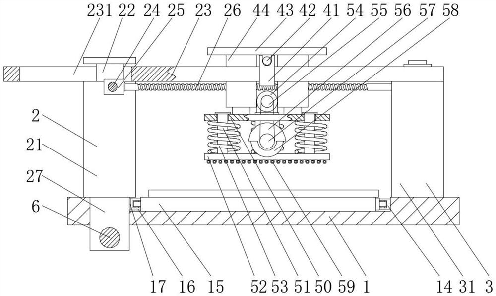
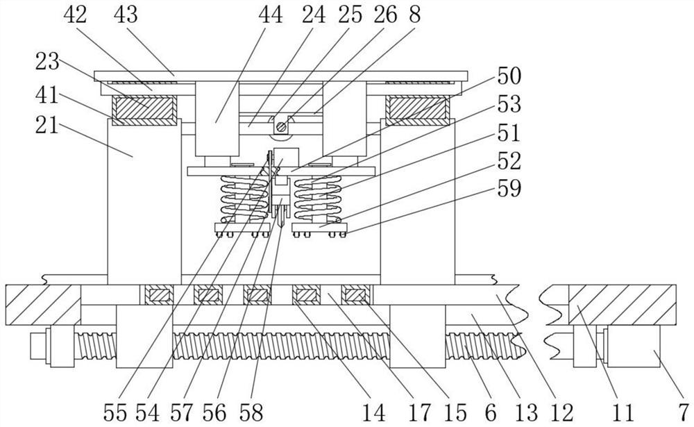
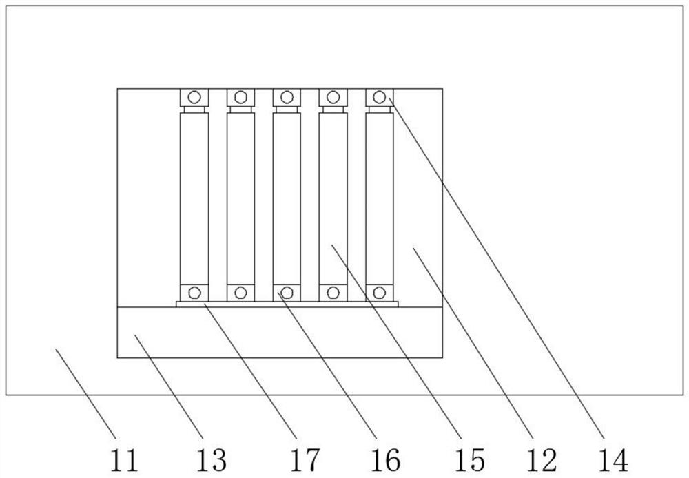
[0028] Such as Figure 1 to Figure 7 As shown, a particleboard directional cutting processing equipment includes a base 1, two moving devices 2 are movably connected to the left side of the base 1, two fixing devices 3 are fixedly connected to the right side of the base 1, and the two moving devices 2 and two There is a corresponding movable connection between the two fixed devices 3, a transmission device 4 is movably connected between the mobile device 2 and the fixed device 3, the bottom of the transmission device 4 is fixedly equipped with a cutting device 5, and the lower part of the base 1 is located on one side of the mobile device 2 and passes through The suspension ring is movably connected with a second screw rod 6, the bottom of the base ...


PUM


Abstract

The invention relates to a particleboard directional cutting processing equipment, comprising a base, two moving devices are movably connected to the left side of the base, two fixing devices are fixedly connected to the right side of the base, the two moving devices are connected to the two Corresponding movable connections between the two fixing devices, the particleboard directional cutting processing equipment is provided with two mobile support columns that can be driven vertically by a third motor in the horizontal direction at one end of the base, and the movement of the mobile support columns It can drive the circular slot at one end of the linkage rod to rotate around the top of the fixed support column, and the long slot at the other end slides in the slot to realize the angle change of the upper part of the overall equipment, thereby driving the transmission device and the cutting device Rotation at the same angle occurs, so that the equipment can directly perform bevel or other shape cutting requirements in one processing process, which greatly increases the applicability of the equipment.

Description

technical field [0001] The invention relates to the technical field of particle board processing, in particular to a device for directional cutting and processing of particle boards. Background technique [0002] Particleboard is also called particle board. It is a wood-based panel made of wood or other woody cellulose materials, which are glued together under heat and pressure after applying adhesives. It is widely used in home manufacturing and construction industries as well as trains and automobiles. For the manufacture of the compartment, the particleboard is cut into corresponding blocks as required. [0003] The existing cutting devices for particleboard can only cut the particleboard in a fixed direction, basically cutting the particleboard into segments, but in actual production needs, it is often necessary to cut off the corners of the particleboard or cut out some other required parts. However, the existing equipment, whether it is a cutter or a fixed fixture, ca...

Claims


Application Information

Patent Timeline
Patent Type & Authority Patents(China)
IPC IPC(8): B27C5/02
CPCB27C5/02
Inventor 潘仲民
Owner 广东国景家具集团有限公司
Learn More