Thickness setting device of continuous foaming material

A technology of foaming materials and foaming chambers, which is applied in thin material processing, coiling strips, transportation and packaging, etc., and can solve problems such as affecting bonding, slow cooling speed, and excessive sheet extrusion

Active Publication Date: 2020-10-30
ZHEJIANG RUNYANG NEW MATERIAL TECH
View PDF12 Cites 1 Cited by
  • Summary
  • Abstract
  • Description
  • Claims
  • Application Information

AI Technical Summary

Problems solved by technology

In the above-mentioned process, the cooling and shaping process is particularly important, which directly determines the quality of the finished product. Most of the shaping devices of the existing foaming material production line are cooling roller groups (such as CN105599210B, CN209111359U) located outside the foaming furnace, and have the following defects: one is The cooling speed is slow, although it can be improved by increasing the number of cooling roller groups or increasing the pressure on the rollers, but the former consumes a lot of energy and the latter is easy to over-extrude or even break the sheet; more importantly, the

Method used


Image

  • Thickness setting device of continuous foaming material
  • Thickness setting device of continuous foaming material
  • Thickness setting device of continuous foaming material

Examples


Embodiment 1

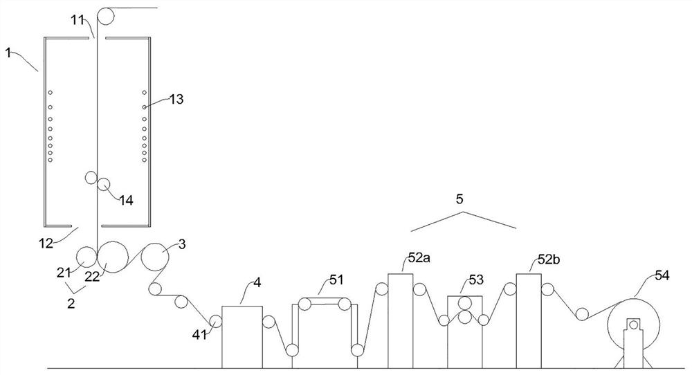
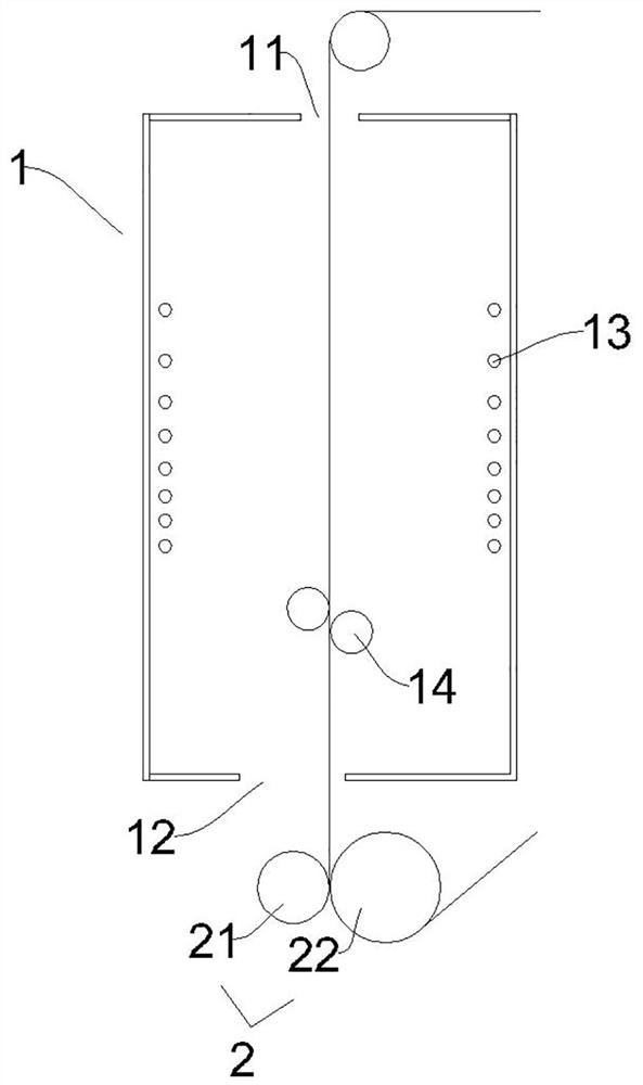
[0038] A thickness setting device for continuous foaming materials, such as figure 1 As shown, it includes a foaming chamber 1 and a thickened part 2; in this embodiment, the foaming chamber 1 is a vertical foaming chamber, and the upper and lower ends are respectively provided with a feed port 11 and a discharge port 12, and the foaming chamber The inner wall of 1 is provided with several heating elements 13 along the conveying direction of the foaming material, and the heating elements 13 are arranged in the middle of the inner wall of the foaming furnace 1, and an unfolding roller 14 is arranged under the area where the heating elements 13 are arranged, and the inside of the unfolding roller 14 is Hollow, and equipped with cooling water inlet.

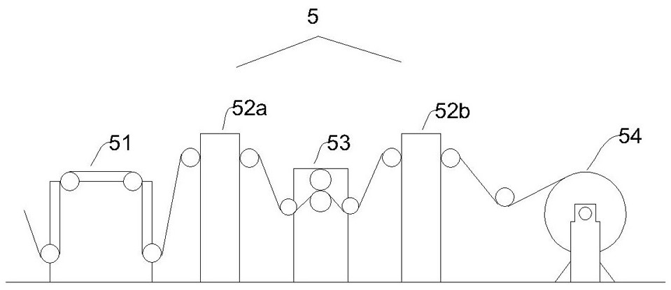
[0039] The thickening part 2 is arranged on the outside of the discharge port 12, such as Figure 1-2 As shown, it includes a pressure roller 21 and a turning roller 22 that are provided with a cooling structure 23 on the opposite ...

Embodiment 2

[0042] A production equipment for continuous foaming materials, the basic structure of which is the same as that of Embodiment 1, the difference is that in this embodiment only a cooling structure 23 is provided on the surface of the pressure roller 21 .

Embodiment 3

[0044] A continuous foaming material production equipment, the basic structure is the same as embodiment 1, the difference is: the foaming chamber 1 of this embodiment is a horizontal foaming chamber, such as image 3 As shown, the left and right ends of the foaming chamber 1 are respectively provided with a material inlet 11 and a material outlet 12, and the embossing roller 21 and the turning roller 22 are arranged opposite to each other up and down, and the rest of the structure is the same as that of Embodiment 1.


PUM


Abstract

The invention belongs to the technical field of production equipment of foaming materials, and particularly discloses a thickness setting device of a continuous foaming material. The thickness settingdevice comprises a foaming cavity and a thickness locking part, wherein the two ends of the foaming cavity are provided with a feeding port and a discharging port respectively, several heating elements are arranged on the inner wall of the foaming cavity in the conveying direction of the foaming material, the thickness locking part is arranged outside the discharging port, and comprises a pressure roll and a steering roll which are oppositely arranged and communicate with a cooling medium pipeline, the surface of at least one of the pressure roll and the steering roll is provided with a cooling structure, at least one of the pressure roll and the steering roll is a driving roll driven by power equipment to rotate, and the foaming material is conveyed out in a way of fitting the surface ofthe steering roll after passing by a pressing area between the pressure roll and the steering roll. By means of the thickness setting device, precise and quick thickness setting of the foaming material can be achieved, dimensional deviation of the finished product is effectively lowered, and the quality of the finished product is improved.

Description

technical field [0001] The invention belongs to the technical field of foaming material production equipment, and in particular relates to a thickness setting device for continuous foaming materials. Background technique [0002] Sheet foaming refers to the process of heating a strip-shaped polymer material in a foaming furnace, and the foaming agent decomposes at high temperature to generate gas, fills the inside of the polymer material, and produces a foaming material with closed pores. In production, after the foaming is completed, the foaming material needs to be cooled and shaped by a cooling device, and then rolled directly or after some post-processing procedures (such as edge trimming, embossing, cutting, etc.) to obtain the finished product. In the above-mentioned process, the cooling and shaping process is particularly important, which directly determines the quality of the finished product. Most of the shaping devices of the existing foaming material production li...

Claims


Application Information

Patent Timeline
IPC IPC(8): B29C44/20B29C44/34B29C44/60B29C59/10B65H23/038B65H23/26B29L7/00
CPCB65H23/038B65H23/26B29C44/203B29C44/3442B29C44/3415B29C44/60B29C59/10B29L2007/002
Inventor 万立祥杨庆锋张镤
Owner ZHEJIANG RUNYANG NEW MATERIAL TECH
Why Eureka
Try Eureka