Flat-plate conveying device

A conveying device and flat plate technology, which is applied in the direction of conveyor objects, transportation and packaging, and object destacking, etc., which can solve the problems of medical staff fatigue, time-consuming and labor-intensive, antibiotic abuse, etc.

Pending Publication Date: 2020-10-30
JIANGSU SKYRAY INSTR
View PDF6 Cites 3 Cited by
  • Summary
  • Abstract
  • Description
  • Claims
  • Application Information

AI Technical Summary

Problems solved by technology

[0002] At present, in the medical field, people's health and corresponding awareness are getting more and more attention from all aspects. Antibiotics have a very significant effect on the medical field and people's health. However, due to the lack of understanding of antibiotics in the past, the use of antibiotics has appeared. The situation of abuse has brought a certain negative impact on the health of the people. Therefore, when the people are sick, medical workers will gradually adopt more scientific and robust methods and methods to treat patients. The current practice is, Collect the patient's body fluid sample, put it into a special test tube for backup, and then use the inoculation loop to apply the spare body fluid on the corresponding position on the plate and culture it. After a certain period of time, observe and test the cultured body fluid in order to understand the true state of the patient. The current methods and methods are manual operation, which is not only time-consuming and labor-intensive, but also due to the possibility of fatigue of medical staff, it is easy to cause certain mistakes, so it is necessary to find an automated method. methods and methods, and the use of automated methods and methods, it is necessary to judge whether the flat plate transmission involved and determine whether it is missing during the transmission process, so it is necessary to design a corresponding structure to solve such problems

Method used


Image

  • Flat-plate conveying device
  • Flat-plate conveying device
  • Flat-plate conveying device

Examples


Embodiment Construction

[0017] The following describes the embodiments of the present invention in detail. Examples of the embodiments are shown in the accompanying drawings, wherein the same or similar reference numerals indicate the same or similar elements or elements with the same or similar functions; the following implementations are described with reference to the accompanying drawings. The examples are exemplary, and are only used to explain the present invention, but cannot be construed as limiting the present invention.

[0018] In the description of the present invention, it should be understood that the terms "upper", "lower", "bottom", "top", "front", "rear", "inner", "outer", "horizontal", " The orientation or positional relationship indicated by "vertical" is based on the orientation or positional relationship shown in the drawings, and is only for the convenience of describing the present invention and simplifying the description, and does not indicate or imply that the device or element ...


PUM


Abstract

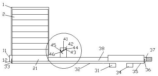
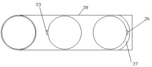
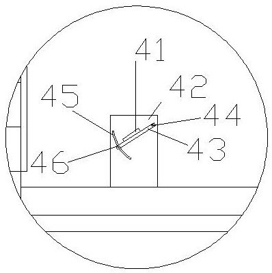
The invention discloses a flat-plate conveying device. The flat-plate conveying device comprises a stacking tank for placing flat plates; the lower part of the stacking tank is mounted on a bottom guiding component at the lower part; the bottom guiding component comprises an outlet allowing the flat plates to enter or leave; a supporting plate for supporting the flat plates and a transfer device for pushing out the flat plates through a telescopic stop block are arranged below the bottom guiding component; the transfer device comprises a transfer connection component and a transfer power source which are connected with the telescopic stop block as well as a transfer guiding component for restraining the conveying direction of the flat plates; one side of the transfer guiding component is connected with the outlet, and a terminal flat-plate chamber used as the conveying end point of the flat plates is arranged on the other side; and a clamping device for clamping the flat plates is arranged below the terminal flat-plate chamber and comprises a clamping power source, a clamping component and a clamping connection component connected between the clamping power source and the clampingcomponent. According to the flat-plate conveying device, the labor can be reduced, so that the automation degree can be greatly increased, and the efficiency can be greatly improved.

Description

Technical field [0001] The invention relates to the field of medical automation, in particular to a flat-plate conveying device. Background technique [0002] At present, in the medical field, people’s health and corresponding awareness are getting more and more attention from all aspects. Antibiotics are very effective in the medical field and on people’s health. However, due to insufficient understanding of antibiotics in the past, the use of antibiotics has appeared. The abuse has brought a certain negative impact on the health of the people. Therefore, when the people are sick, medical workers will gradually adopt more scientific and stable methods and methods to treat patients. The current practice is: Collect the patient’s body fluid sample, put it in a special test tube, and then use the inoculation loop to apply the spare body fluid to the corresponding position in the plate and culture it. After a certain period of time, observe and test the cultured body fluid to under...

Claims


Application Information

Patent Timeline
IPC IPC(8): B65G47/06B65G59/06
CPCB65G47/06B65G59/067
Inventor 刘召贵周晓辉邓东卫周专武凤翠唐勇刚
Owner JIANGSU SKYRAY INSTR
Why Eureka
Try Eureka