Warp knitting machine and method for operator assistance in a warp knitting machine

A warp knitting machine and warp beam technology, applied in the field of warp knitting machines, can solve time-consuming and cumbersome problems

Active Publication Date: 2020-10-30
KARL MAYER STOLL R&D GMBH
View PDF9 Cites 0 Cited by
  • Summary
  • Abstract
  • Description
  • Claims
  • Application Information

AI Technical Summary

Problems solved by technology

This is tedious and quite time consuming

Method used


Image

  • Warp knitting machine and method for operator assistance in a warp knitting machine
  • Warp knitting machine and method for operator assistance in a warp knitting machine
  • Warp knitting machine and method for operator assistance in a warp knitting machine

Examples


Embodiment Construction

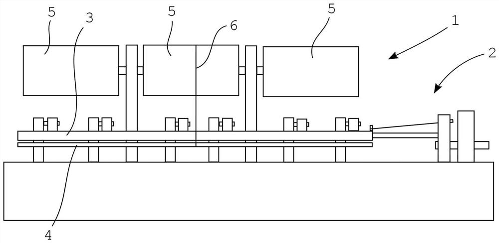
[0050] figure 1 A schematic diagram of a warp knitting machine 1 with a tensioned spring tension system 2 according to the invention is shown. The warp knitting machine 1 has a guide bar 3 and a needle bar 4 . Warp yarns 6 are loaded on a plurality of warp beams 5 of the warp knitting machine 1, wherein figure 1Only one warp thread 6 is shown by way of example. The warp yarn 6 is guided from the warp beam 5 to the guide bar 3 . Beneath the guide bar 3 , the warp threads 6 are hooked by the not shown knitting needles of the needle bar 4 during the knitting process and knitted into a cloth.

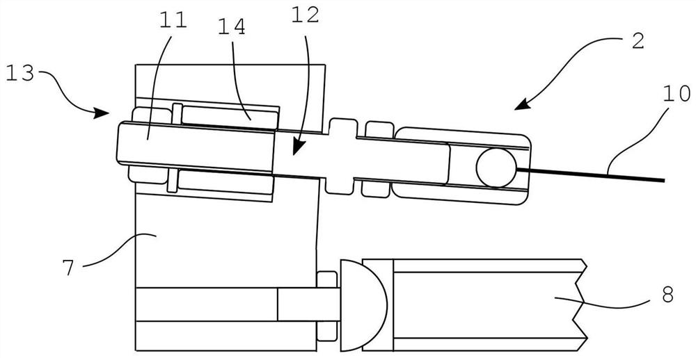
[0051] figure 2 A schematic diagram of the spring tension system 2 of the warp knitting machine 1 with the pusher 7 , the push rod 8 and the stop 9 is shown. exist figure 2 The thread guide bar 3 , which is only partially shown in FIG. 2 , must be moved along its longitudinal axis during the knitting process. This movement is brought about by a not shown drive of the warp knitting ...


PUM


Abstract

The invention relates to a warp knitting machine having a yarn guide bar (3), a push rod (8) and a spring pull system (2) which can pull the yarn guide bar (3) towards the push rod (8) and press it against the push rod. According to the invention, the warp knitting machine (1) has a drive which can act on the spring pull system (2), so that the pulling force applied to the yarn guide bar (3) by the spring pull system (2) is changed. The invention also relates to a method for operator assistance in the warp knitting machine (1), in which, according to the invention, a drive of the warp knittingmachine (1) acts on a spring pull system (2) of the warp knitting machine (1) such that the tension applied by the spring-pull system (2) to a yarn guide bar (3) of the warp knitting machine (1) is changed.

Description

technical field [0001] The invention relates to a warp knitting machine with a guide bar, a pusher bar and a spring pulling system which pulls the guide bar towards the pusher bar and compresses it to the pusher bar. Background technique [0002] Such warp knitting machines are known from the prior art. Therefore, CN205676612U shows an arrangement which allows the yarn guide bar to be driven by a push rod. The jacquard device is used to move the guide bar longitudinally, which moves the push rod. The spring pull system in this arrangement consists of a pull cord to which the spring applies tension. The pull cord transmits the pulling force to the yarn guide bar, thereby compressing the yarn guide bar to the push rod. [0003] The warp yarn required for warp knitting is provided by the warp beam of the warp knitting machine. It is necessary to remove the guide bar for warp beam replacement. In order to remove the yarn guide bar, first the pull cord must be disengaged fro...

Claims


Application Information

Patent Timeline
IPC IPC(8): D04B27/32
CPCD04B27/32D04B27/26D04B27/24D04B27/14
Inventor K·布兰德C·施奈德
Owner KARL MAYER STOLL R&D GMBH
Why Eureka
Try Eureka