
Disk spring assembly, motorized spindle, machining equipment

A technology of electric spindle and disc spring, which is applied in the direction of metal processing equipment, mechanical equipment, metal processing machinery parts, etc., can solve the problems of cumbersome installation process, affecting the performance of the disc spring body, difficulties, etc.

Active Publication Date: 2020-10-30
GREE ELECTRIC APPLIANCES INC
View PDF22 Cites 0 Cited by
  • Summary
  • Abstract
  • Description
  • Claims
  • Application Information

AI Technical Summary

Problems solved by technology

[0003] At present, there are many types of disc springs, such as ordinary rectangular cross-section disc springs, rectangular cross-section disc springs, trapezoidal cross-section disc springs, slotted disc springs, and diaphragm disc springs, most of which are standardized ordinary rectangular cross-sections. The disc spring body, the cross-sectional shape and fixing method of the disc spring body directly affect the performance of the disc spring body, and there are still some deficiencies in the prior art: when the disc spring body is stacked and combined, it must have an inner guide or an outer guide and other external guiding devices, this conventional fixing method is difficult to use in some special occasions, and the installation process is extremely cumbersome and difficult

Method used


Image

  • Disk spring assembly, motorized spindle, machining equipment
  • Disk spring assembly, motorized spindle, machining equipment
  • Disk spring assembly, motorized spindle, machining equipment

Examples


Embodiment Construction

[0043] The first embodiment of disc spring assembly and electric spindle

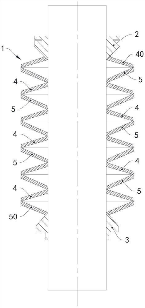
[0044] see figure 1 , The electric spindle includes a disc spring assembly 1 , a first work piece 2 , a second work piece 3 and a pull rod 3 .

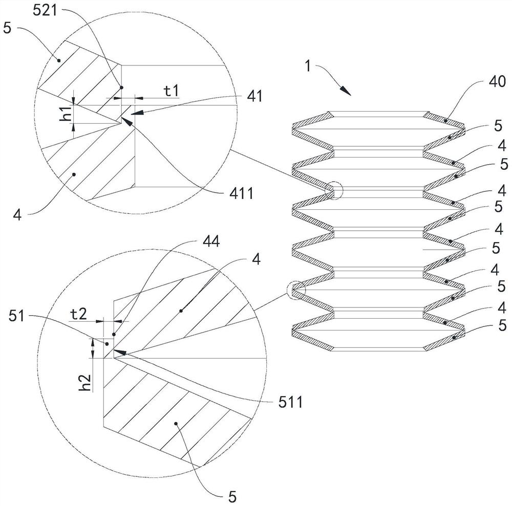
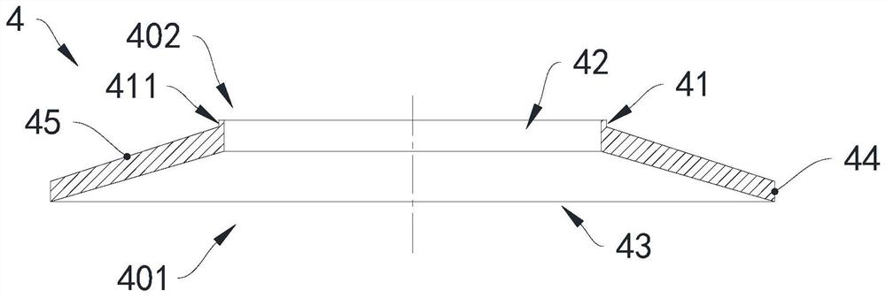
[0045] Disc spring assembly 1 includes six first disc spring bodies and six second disc spring bodies coaxially arranged, and the first disc spring bodies and the second disc spring bodies are arranged alternately along the axis, because the first disc spring body and the second disc spring body are arranged alternately along the axis, because the first disc spring body located at the end The structures of the remaining five first disc spring bodies outside a disc spring body are identical, and the structures of the remaining five second disc spring bodies except the second disc spring body at the end are identical. For ease of description, they are arranged at the end The first disc spring body is the first disc spring body 40, the remaining five first disc s...


PUM


Abstract

The invention provides a disc spring assembly, a motorized spindle and machining equipment. The disc spring assembly comprises first disc spring bodies and second disc spring bodies coaxial with the first disc spring bodies. The first disc spring bodies are provided with first bosses which are revolution bodies formed in the mode that first rectangular surfaces rotate by one circle around the axes, the first bosses extend in the directions away from first openings in the axial directions, and first central holes are formed in the first disc spring bodies in a penetrating mode in the axial direction. Second central holes are formed in the second disc spring bodies in a penetrating mode in the axial directions, second bosses are arranged at the first axial ends of the second disc spring bodies, the second bosses are revolution bodies formed in the mode that second rectangular surfaces rotate by one circle around the axes, and the second bosses extend in the directions away from the second central holes in the axial directions. The inner circumferential walls of the second central holes abut against the outer circumferential walls of the first bosses of the adjacent first disc springbodies. The inner circumferential walls of the second bosses abut against the outer circumferential walls of the first axial ends of the adjacent disc spring bodies. The disc spring assembly can achieve automatic guiding positioning, the matching compactness can be improved, and the bearing fore can be improved.

Description

technical field [0001] The invention relates to the technical field of an electric spindle, in particular to a disc spring assembly, an electric spindle and processing equipment. Background technique [0002] The disc spring assembly consists of multiple stacked disc spring bodies. Each disc spring body is in the shape of a flat conical disc. Unlike traditional springs, the disc spring body is a kind of spring washer. The main features are: large load and short stroke , The required space is small, the combination is convenient, the maintenance and replacement are easy, the economy and safety are high, and the service life is long. [0003] At present, there are many types of disc springs, such as ordinary rectangular cross-section disc springs, rectangular cross-section disc springs, trapezoidal cross-section disc springs, slotted disc springs, and diaphragm disc springs, most of which are standardized ordinary rectangular cross-sections. The disc spring body, the cross-se...

Claims


Application Information

Patent Timeline
IPC IPC(8): F16F1/32B23B19/02
CPCB23Q1/70F16F1/32
Inventor 姚杰刘伟健卓明张智超刘建国吴世历
Owner GREE ELECTRIC APPLIANCES INC
Learn More