Air cylinder control valve

A technology of cylinder control and valve stem, applied in the field of control valves

Active Publication Date: 2020-10-30
HUBEI WATERWEI AUTOMOTIVE ELECTRONICS
View PDF11 Cites 0 Cited by
  • Summary
  • Abstract
  • Description
  • Claims
  • Application Information

AI Technical Summary

Problems solved by technology

[0005] In order to solve the above technical problems, a cylinder control valve is provided. This technical solution solves the problem that the control valve adjusts the gas flow rate

Method used


Image

  • Air cylinder control valve
  • Air cylinder control valve
  • Air cylinder control valve

Examples


Embodiment Construction

[0039] The following description serves to disclose the present invention to enable those skilled in the art to carry out the present invention. The preferred embodiments described below are only examples, and those skilled in the art can devise other obvious variations.

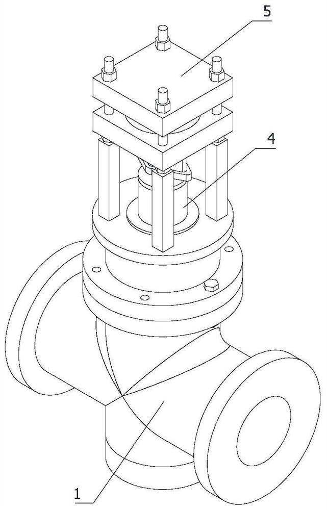
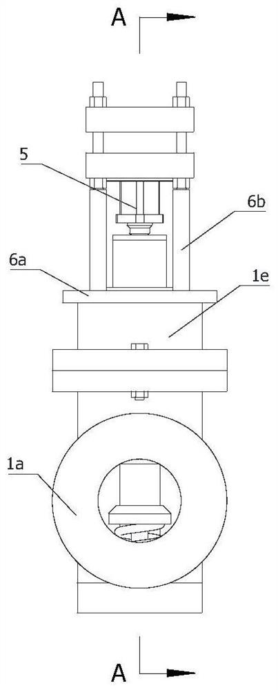
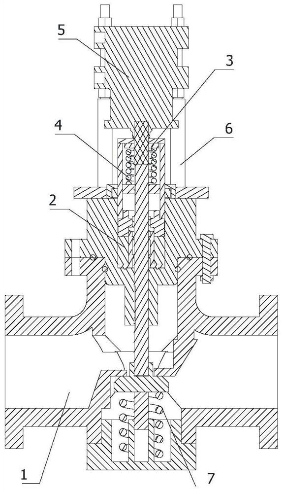
[0040] refer to image 3As shown, a cylinder control valve includes: a two-way regulating valve 1, in the working state, the working rod of the two-way regulating valve 1 moves downward in the axial direction and is in an open state; the sealing pressing member 2 is arranged on Inside the top of the two-way regulating valve 1, the working rod of the two-way regulating valve 1 is coaxially sliding and sealingly matched with the sealing pressing part 2; the limit ring 3 is coaxially arranged on the top of the working shaft of the two-way regulating valve 1; the adjustable elastic The movable part 4, the adjustable elastic movable part 4 is coaxially arranged on the top of the sealing pressing part 2, and the ...


PUM


Abstract

The invention belongs to the field of control valves, and specifically relates to an air cylinder control valve. The air cylinder control valve comprises a two-way adjusting valve, a sealing pressingpiece, a limiting ring, an adjustable elastic moving part and an electric telescopic rod, wherein an operating rod of the two-way adjusting valve moves downwards in an axial direction in an operatingstate, and the two-way adjusting valve is open; the sealing pressing piece is arranged in the top end of the two-way adjusting valve, and the operating rod of the two-way adjusting valve is in slidingseal fit with the sealing pressing piece coaxially; the limiting ring is coaxially arranged on the top end of an operating shaft of the two-way adjusting valve; the adjustable elastic moving part iscoaxially arranged on the top end of the sealing pressing piece, and the limiting ring is coaxially located on the elastic abutting end of the interior of the adjustable elastic moving part; and the electric telescopic rod and the sealing pressing piece are coaxially arranged on the top end of the two-way adjusting valve by virtue of a fixed frame, and an output shaft of the electric telescopic rod coaxially penetrates through the top end of the adjustable elastic moving part and is coaxially and fixedly connected with the top end of the limiting ring. The air cylinder control valve has the advantage of a stable structure, and the flow speed of air can be adjusted.

Description

technical field [0001] The invention relates to the field of control valves, in particular to a cylinder control valve. Background technique [0002] The cylinder control valve is a very important terminal component in the automatic control system. It is used to adjust the gas flow to the cylinder. The actuator of the control valve can withstand high air source pressure, large thrust, fast stroke speed, and is durable. Cylinder output shaft extension rates can be varied by a control valve capable of adjusting the gas flow rate. [0003] Chinese patent CN201620946783.7 discloses a cylinder-type straight-through control valve, which includes a valve body and a valve core. There is a liquid chlorine flow channel in the valve body, and inlets and outlets connected to the liquid chlorine flow channel are arranged on both sides of the valve body. The valve core Including the valve core body and the valve seat, the horizontally placed U-shaped valve seat is installed in the middle...

Claims


Application Information

Patent Timeline
Patent Type & Authority Applications(China)
IPC IPC(8): F16K1/04F16K1/32F16K31/02F16K31/50F16K41/02
CPCF16K1/04F16K1/32F16K41/02F16K31/02F16K31/50
Inventor 王艳萍
Owner HUBEI WATERWEI AUTOMOTIVE ELECTRONICS
Why Eureka
Try Eureka