High-precision lens anti-blue-ray detector

An anti-blue light, high-precision technology, applied in the direction of testing optical performance, etc., can solve the problems that affect the use of the detection device, the cumbersome process of disassembly and detection, and the inability to detect the position display, etc., to achieve accurate accuracy, reduce the difficulty of repair, and facilitate observation and inspection. The effect of repair

Pending Publication Date: 2020-10-30
NANNING UNIV
View PDF0 Cites 0 Cited by
  • Summary
  • Abstract
  • Description
  • Claims
  • Application Information

AI Technical Summary

Problems solved by technology

[0003] There are certain disadvantages in the use of the existing lens anti-blue light detector, 1: the detection position cannot be displayed, although the existing lens anti-blue light detector can emit blue light when detecting, but the human eye cannot see the edge of the blue light , when the lens is inspected, the position of the blue light irradiation cannot be accurately understood, so that the inspector cannot timely understand those positions of the lens that have not been inspected, which affects the use of the detection device; 2: the existing anti-blue light detector for the lens is repaired , the device can only be repaired after the shell of the device is disassembled with tools. The process of disassembly and detection is too cumbersome, which affects the timely use of the anti-blue light detector of the lens; 3: the anti-blue light lens detector in the prior art can only simultaneously Carry out a group of lens testing, and judge the anti-blue light effect of the lens through whether there is blue light passing through the white background, no specific data index data reference

Method used


Image

  • High-precision lens anti-blue-ray detector
  • High-precision lens anti-blue-ray detector
  • High-precision lens anti-blue-ray detector

Examples


Embodiment

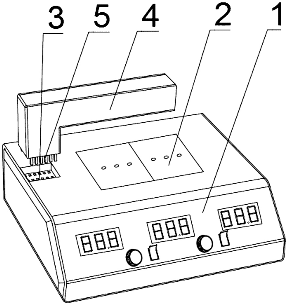
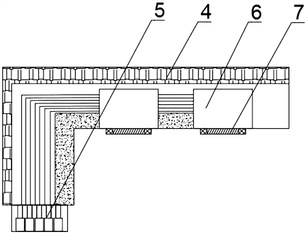
[0027] like Figure 1-5 As shown, the present invention provides a high-precision lens anti-blue light detector, including a protective housing 1, a receiving plate 2 is fixedly installed at the center of the top outer surface of the protective housing 1, and a plurality of through-holes are provided on the top outer surface of the receiving plate 2. hole, the top outer surface of the protective shell 1 is provided with a docking groove 3 near one side, and the inner surface of the docking groove 3 is movably installed with a detection frame 4, and the side of the detection frame 4 near the docking groove 3 is welded with a docking pin. A plurality of copper pins 5 are welded on the outer surface of the bottom end of the test frame 4, and a transmitter 6 is fixed and installed by bolts at a position close to the receiving plate 2 inside the detection frame 4.

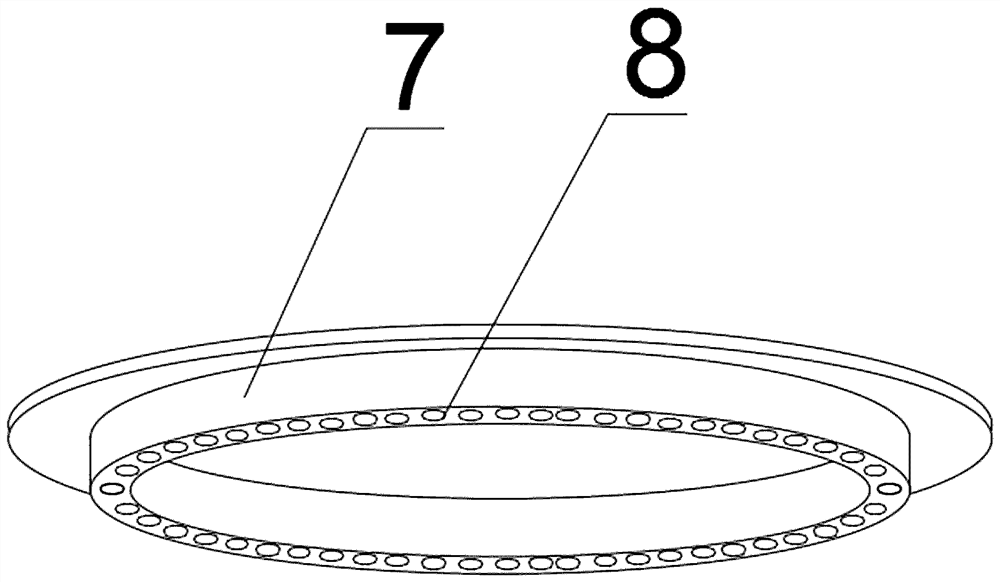
[0028] refer to image 3 As shown, a detection ring 7 is fixedly installed on the outer surface of the bottom end of...


PUM


Abstract

The invention provides a high-precision lens anti-blue-ray detector. The detector comprises a protective shell, a receiving plate is fixedly installed in the center of the outer surface of the top endof the protective shell, a plurality of through holes are formed in the outer surface of the top end of the receiving plate, and a butt joint groove is formed in the position, close to one side, of the outer surface of the top end of the protective shell. The invention relates to the high-precision lens anti-blue-ray detector. A plurality of blue light lamps emit light at the same time to form anannular aperture; the emission range of the emitter is displayed, which is convenient for a user to determine irradiation position and know the current detection position of the lens in time; an electromagnetic plate is powered on to generate magnetism, a plug pin at the top end is attracted in the direction of the electromagnetic plate, the plug pin is moved out of a fixing groove in the protective shell, then the protective shell is opened, all components installed on an installation plate are displayed in front of maintenance personnel, observation and maintenance of the maintenance personnel are facilitated, and the maintenance difficulty is reduced.

Description

technical field [0001] The invention relates to the field of lens detection, in particular to a high-precision lens anti-blue light detector. Background technique [0002] Anti-blue light glasses are glasses that can prevent blue light from irritating the eyes. Special anti-blue light glasses can effectively isolate ultraviolet rays and radiation and filter blue light. They are suitable for use when watching computers or TV phones; [0003] There are certain disadvantages in the use of the existing lens anti-blue light detector, 1: the detection position cannot be displayed, although the existing lens anti-blue light detector can emit blue light when detecting, but the human eye cannot see the edge of the blue light , when the lens is inspected, the position of the blue light irradiation cannot be accurately understood, so that the inspector cannot timely understand those positions of the lens that have not been inspected, which affects the use of the detection device; 2: th...

Claims


Application Information

Patent Timeline
IPC IPC(8): G01M11/02
CPCG01M11/02
Inventor 梁承权吕德深黄世玲
Owner NANNING UNIV
Why Eureka
Try Eureka