Feeding mechanism

A feeding mechanism and sample feeding technology, applied in analytical materials, instruments, etc., can solve the problems of pollution reflecting the environment, easy sample jam, and high noise of the sample feeding tray.

Pending Publication Date: 2020-10-30
长沙开元仪器有限公司
View PDF0 Cites 1 Cited by
  • Summary
  • Abstract
  • Description
  • Claims
  • Application Information

AI Technical Summary

Problems solved by technology

[0005] The purpose of the present invention is to provide a feeding mechanism, the purging device realizes the movement of the sample between the three positions of the sample feeding position, the purging position and the sample dropping position, and realizes automatic sample feeding, zero blank purging and automatic sample dropping, It solves the problems of high noise, large fluctuations and easy jamming of the sample delivery tray, and also solves the problem of air interference particles entering the combustion chamber to pollute and reflect the environment

Method used


Image

  • Feeding mechanism
  • Feeding mechanism
  • Feeding mechanism

Examples


Embodiment Construction

[0020] The following will clearly and completely describe the technical solutions in the embodiments of the present invention with reference to the accompanying drawings in the embodiments of the present invention. Obviously, the described embodiments are only some, not all, embodiments of the present invention. Based on the embodiments of the present invention, all other embodiments obtained by persons of ordinary skill in the art without making creative efforts belong to the protection scope of the present invention.

[0021] In order to enable those skilled in the art to better understand the solution of the present invention, the present invention will be further described in detail below in conjunction with the accompanying drawings and specific embodiments.

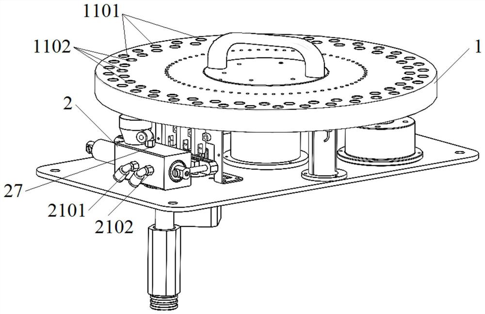
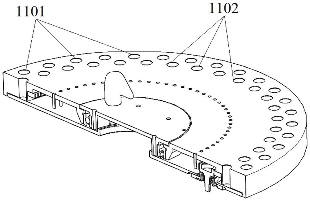
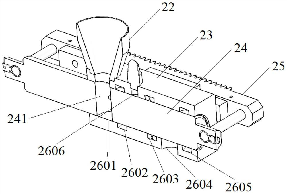
[0022] Please refer to Figure 1 to Figure 3 ,in, figure 1 Schematic diagram of the structure of the feeding mechanism provided by the embodiment of the present invention, figure 2 for figure 1 Schematic diagram...


PUM


Abstract

The invention discloses a feeding mechanism. The feeding mechanism comprises a sample feeding disc which is driven by a motor to rotate, a plurality of sample holes are formed along the circumferenceof the sample feeding disc; a purging device is arranged under the circumference of the sample feeding disc; the purging device comprises a valve body and a valve rod capable of moving in the valve body. The valve rod is provided with a sample containing groove, and the valve body is sequentially provided with a first groove position used for allowing the valve rod to achieve sample feeding at thesample feeding position, a sixth groove position used for allowing the valve rod to achieve sample purging at the purging position and a fourth groove position used for allowing the valve rod to achieve sample falling at the sample falling position. The purging device of the feeding mechanism realizes movement of a sample among three positions including the sample feeding position, the purging position and the sample falling position, realizes automatic sample feeding, zero-blank purging and automatic sample falling, solves the problems of large noise, large fluctuation and easiness in sampleblockage of a sample feeding disc, and also solves the problem that air interferes with particles entering a combustion chamber to pollute a reaction environment.

Description

technical field [0001] The invention relates to the technical field of conveying operations, in particular to a feeding mechanism. Background technique [0002] The sample delivery mechanism is commonly used in the automatic sample delivery of laboratory elemental analysis instruments. It mainly realizes the automatic sequential sampling of samples, the purging of samples into the air, and the automatic fall of samples into the combustion chamber. [0003] The existing sample delivery mechanism is a slider structure, the sample delivery tray pushes the slider through the cylinder, and the ratchet mechanism on the slider pushes the stop pin connected to the sample tray to realize the index feeding of the sample tray; the slider Load the sample into the furnace door plug, then restore the sealing position, purge the sample with the purge gas, and exhaust the exhaust gas through the combustion chamber, and finally the furnace door plug cylinder moves to release the sample into ...

Claims


Application Information

Patent Timeline
Patent Type & Authority Applications(China)
IPC IPC(8): G01N35/10G01N35/02
CPCG01N35/025G01N35/1083G01N2035/0441
Inventor 袁康周磊徐开群罗建文
Owner 长沙开元仪器有限公司
Why Eureka
Try Eureka