Supercharge Your Innovation With Domain-Expert AI Agents!

A micro-lens array optical projection system

A microlens array and optical projection technology, applied in the field of projection systems, can solve problems such as mutual crosstalk, projected real image double image, single projected real image, etc., to achieve the effect of avoiding cross-light and double image

Active Publication Date: 2021-03-30
YEJIA OPTICAL TECH GUANGDONG CORP
View PDF5 Cites 0 Cited by
  • Summary
  • Abstract
  • Description
  • Claims
  • Application Information

AI Technical Summary

Problems solved by technology

[0005] Multi-channel projection systems such as figure 2 As shown, including the light source, collimating lens, first microlens array, projection source and second microlens array, far-field imaging can be realized, but when the distance between the receiving surface is relatively short, the height of the microlens unit is higher than that of the projected real image The image height is too large and cannot be ignored. For example, when the ratio of the height of the microlens unit to the height of the projected real image is greater than 1 / 50, due to the offset of each imaging optical path, multiple staggered real image units will be formed on the receiving surface, resulting in In the end, a clear and single projected real image cannot be formed
[0006] In order to solve the above problems, the prior art patent No. 201480039253.8 discloses a multi-aperture projection display and a single image generator for the multi-aperture projection display. figure 2 The center of the second microlens array is offset so that the corresponding optical axis does not coincide with the optical axis of the first microlens array, thereby realizing overlapping and superposition of multi-channel images, and finally realizing short-distance projection and a single projected real image, but Because the optical axis offset of the first microlens array and the second microlens array is staggered, that is, part of the light in a certain unit in the first microlens array enters the adjacent unit of the second microlens array, the distance between adjacent channels The optical information will crosstalk with each other, and eventually cause the projected real image to form a ghost
[0007] The projection system in the prior art cannot ensure that the projected real image is clear and free of ghosting when obtaining close-range projection

Method used


Image

  • A micro-lens array optical projection system
  • A micro-lens array optical projection system
  • A micro-lens array optical projection system

Examples


Embodiment Construction

[0027] In order to further understand the features, technical means, and specific objectives and functions achieved by the present invention, the present invention will be further described in detail below in conjunction with the accompanying drawings and specific embodiments.

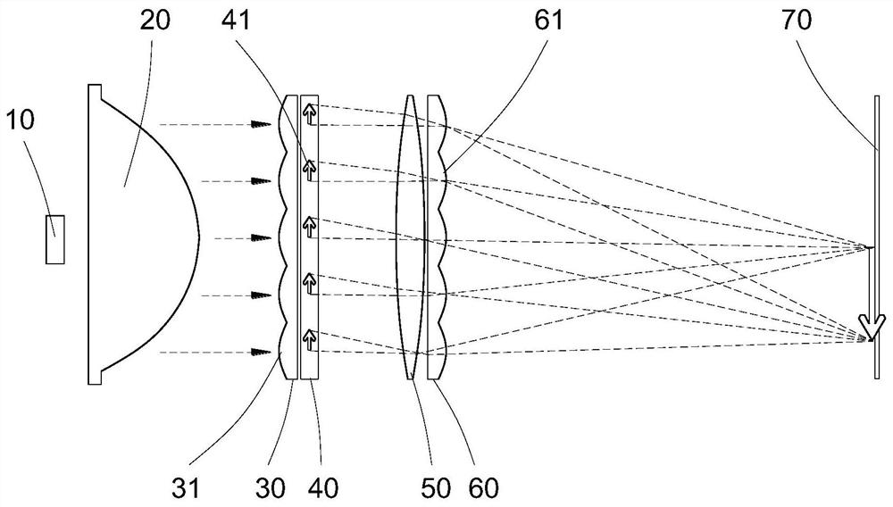
[0028] refer to Figure 3 to Figure 7 .

[0029] The basic embodiment of the present invention discloses an optical projection system of a microlens array, such as image 3 As shown, it includes a light source 10, a collimating lens 20, a first microlens array 30, a projection source 40, a positive lens module 50, a second microlens array 60, and a receiving surface 70 arranged in sequence. The light source 10 can be an LED lamp bead, The projection source 40 can be a film, a liquid crystal screen, etc., the positive lens module 50 is located between the projection source 40 and the second microlens array 60, and the receiving surface 70 can be a wall, the ground, a white screen, etc., and the microle...


PUM


Abstract

The present invention provides an optical projection system of a microlens array, comprising a light source, a collimating lens, a first microlens array, a projection source, a positive lens module, a second microlens array and a receiving surface arranged in sequence, and the first microlens The array includes n first microlens units arranged in an array, the projection source includes n projected image units arranged in an array, and the second microlens array includes n second microlens units arranged in an array; The lens unit and the second microlens unit have a common optical axis; the distance between the projection source and the positive lens module is s, the distance between the second microlens array and the receiving surface is L′, and the equivalent focal length of the positive lens module f 0 =L', the focal length f of the first microlens unit 1 ≈s, the focal length f of the second microlens unit 2 = s. The invention can make the sub-real image units compound and superimpose on the receiving surface, and can avoid the occurrence of cross-light between adjacent optical channels.

Description

technical field [0001] The invention relates to a projection system, and specifically discloses an optical projection system of a microlens array. Background technique [0002] The projection system is an optical system that illuminates the object and images it on the projection screen. The short-distance projection system can be applied to the side of the car to welcome guests, or it can be applied to the front and rear of the car as a warning reminder, and it can also be used for desktop projection, such as the projection of keyboard images. [0003] A projection system mainly includes three important components: a light source, a projection source, and an imaging unit. Based on whether the image in the projection source repeatedly appears on the receiving surface, it is divided into a single-channel projection system and a multi-channel projection system. [0004] Single-channel projection systems such as figure 1 As shown in Fig. 1, a multi-chip imaging unit is set up...

Claims


Application Information

Patent Timeline
Patent Type & Authority Patents(China)
IPC IPC(8): G03B21/14G02B3/00
CPCG03B21/142G02B3/0037G03B21/2033G03B21/2006G03B21/26
Inventor 江程佘俊南基学
Owner YEJIA OPTICAL TECH GUANGDONG CORP
Features
  • R&D
  • Intellectual Property
  • Life Sciences
  • Materials
  • Tech Scout
  • Unparalleled Data Quality
  • Higher Quality Content
  • 60% Fewer Hallucinations
Learn More