
Light machine module and projector

一种光机模块、投影机的技术,应用在光学、光学元件、仪器等方向,能够解决光阀使用寿命降低、温差大内应力、多噪音等问题,达到提高散热效果、佳投影品质的效果

Active Publication Date: 2020-10-30
CORETRONIC
View PDF11 Cites 0 Cited by
  • Summary
  • Abstract
  • Description
  • Claims
  • Application Information

AI Technical Summary

Problems solved by technology

However, this will greatly increase the size of the projector and generate excessive noise
In addition, only installing a heat dissipation module at the rear end of the light valve without effectively cooling the front end of the light valve will cause an excessive temperature difference between the front end of the light valve and the rear end of the light valve, resulting in unexpected internal stress, making the use of the light valve Reduced lifespan

Method used


Image

  • Light machine module and projector
  • Light machine module and projector
  • Light machine module and projector

Examples


Embodiment Construction

[0061] The aforementioned and other technical contents, features and effects of the present invention will be clearly presented in the following detailed description of a preferred embodiment with reference to the accompanying drawings. The directional terms mentioned in the following embodiments, such as: up, down, left, right, front or back, etc., are only referring to the directions of the drawings. Accordingly, the directional terms are used to illustrate and not to limit the invention.

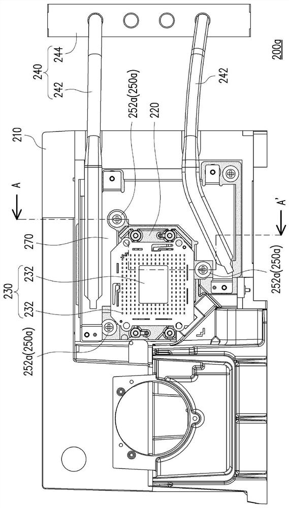
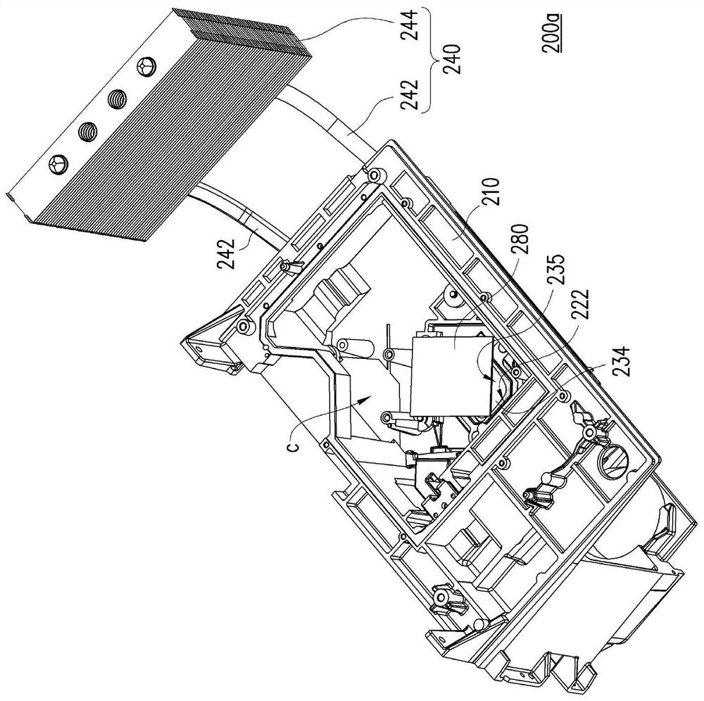
[0062] figure 1 It is a schematic diagram of a projector according to an embodiment of the present invention. Please refer to figure 1 , the projector 10 of this embodiment includes an illumination system 100 , an optical-mechanical module 200 a and a lens 300 . The illumination system 100 is used for providing an illumination beam L1. The light valve 230 of the optical-mechanical module 200a is located on the transmission path of the illumination beam L1 for modulating the illuminati...


PUM


Abstract

The invention provides a light machine module and a projector. The light machine module comprises a shell, an assembly part, a light valve and a first heat exchange assembly, wherein the shell is provided with an assembly port; the assembly part is provided with an opening and is assembled on the shell in a non-direct-contact mode, and the opening corresponds to the assembly port; the light valveis arranged on the assembly part and comprises a base and an imaging element, and the imaging element comprises an imaging surface; the base is supported against the assembly part, and the imaging surface of the imaging element is located at the opening of the assembly; a cavity is defined by the shell, the assembly part and the light valve; the first heat exchange assembly is arranged on the assembly part and comprises at least one first heat conduction piece and first heat dissipation fins; the first heat dissipation fins are located outside the shell; the first heat conduction piece extendsout of the shell from the assembly part and is connected with the first heat dissipation fins. The heat dissipation effect of the front end of the light valve can be improved.

Description

technical field [0001] The invention relates to an optical device and a projector, and in particular to an optical machine module and a projector with the optical machine module. Background technique [0002] The projector uses a light valve to convert the illumination beam from the light source into an image beam, and uses a projection lens to convert the image beam into a projection beam and project it out. As the projection brightness of the projector increases, the heat generated when the light valve acts increases correspondingly. In order to prevent the light valve from overheating, the heat dissipation efficiency of the light valve will be improved by increasing the volume of the heat dissipation module and the speed of the heat dissipation fan. However, this will greatly increase the size of the projector and generate excessive noise. In addition, only installing a heat dissipation module at the rear end of the light valve without effectively cooling the front end ...

Claims


Application Information

Patent Timeline
Patent Type & Authority Applications(China)
IPC IPC(8): G03B21/16G03B21/14
CPCG03B21/16G03B21/145H04N9/3144G03B21/005G03B21/142H05K7/20972H04N9/3197G02B27/0955
Inventor 蔡德颖詹昆洁
Owner CORETRONIC
Learn More