Wear-resistant touch panel with metal net on surface

A touch panel and metal mesh technology, applied in the input/output process of data processing, instruments, calculations, etc., can solve the problems of increased volume, peeling off of protective films such as tempered films, and increased power consumption.

Active Publication Date: 2020-10-30
BEIHAI HIBOSE TECH CO LTD
View PDF15 Cites 1 Cited by
  • Summary
  • Abstract
  • Description
  • Claims
  • Application Information

AI Technical Summary

Problems solved by technology

[0003]In large-scale lectures, usually in order to improve the accuracy of the speech content, a larger touchable display screen is usually set up on the spot. However, as the size of the touchable display screen increases, the internal circuit board increases, and the area in contact with the external electromagnetic wave increases, which makes it very easy for the external electromagnetic wave to affect the circuit board. At the same time, the circuit board itself will also It will affect the touch interface on the display screen, increase the volume, and increase power consumption, which will increase the heat generated by the display itself during operation, resulting in the peeling off of the protective film such as the tempered film on the outer wall, and then When sliding touch, it is easy to cause the sticking position to shift, thus affecting the touch accuracy
[0004] Provide a wear-resistant touch panel with metal mesh on the surface to solve the problem of electromagnetic waves and adhesive peeling off when heated

Method used


Image

  • Wear-resistant touch panel with metal net on surface
  • Wear-resistant touch panel with metal net on surface
  • Wear-resistant touch panel with metal net on surface

Examples


Embodiment Construction

[0024] The following will clearly and completely describe the technical solutions in the embodiments of the present invention with reference to the accompanying drawings in the embodiments of the present invention. Obviously, the described embodiments are only some, not all, embodiments of the present invention. Based on the embodiments of the present invention, all other embodiments obtained by persons of ordinary skill in the art without making creative efforts belong to the protection scope of the present invention.

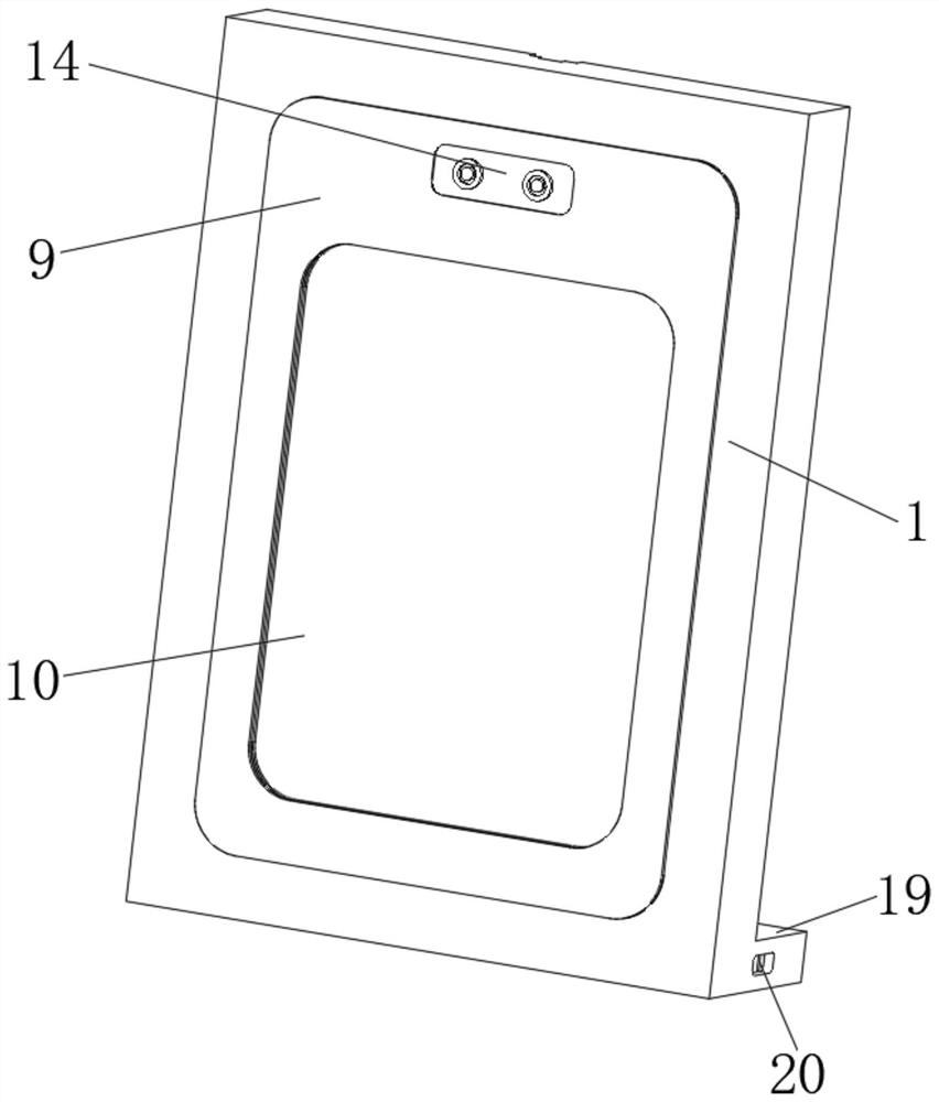
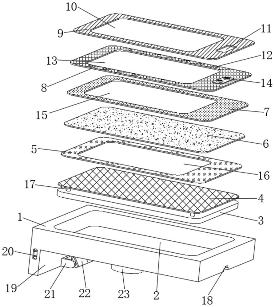
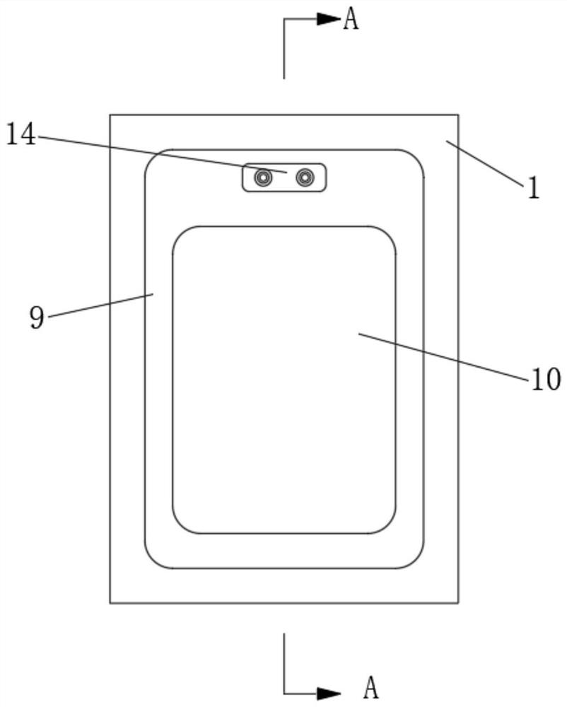
[0025] see Figure 1 to Figure 5 , the present invention provides a technical solution:

[0026] A wear-resistant touch panel with a metal mesh on the surface, comprising an installation frame 1, an installation inner groove 2 is opened in the middle of the front surface of the installation frame 1, and a touch circuit board 3 is installed in the cavity of the installation inner groove 2. Installing the inner groove 2 realizes the fixed installation of the to...


PUM


Abstract

The invention relates to the technical field of touch panels. The invention relates to a touch panel, in particular to a wear-resistant touch panel with a metal net on the surface. The wear-resistanttouch panel comprises a mounting frame, a mounting inner groove is formed in the middle of the front end surface of the mounting frame, and an extending bottom plate is perpendicularly welded to the rear side of the lower end face of the mounting frame. An adjusting sliding groove is vertically and downwards formed in the middle of the rear end face of the mounting frame. A pair of cooling fans are symmetrically arranged on the left and right sides of the rear end surface of the mounting frame. The touch panel is advantageous in that the limiting protrusions corresponding to the tempered pieces are arranged on the outer wall of the display screen, so that the positions of the tempered pieces and the display screen are limited easily, it is avoided that when mucilage glue is heated, the viscosity is reduced, and consequently a protective film deviates; and the metal net and the wave absorbing layer are arranged to be matched at intervals, so that the influence of a circuit board and external electromagnetic waves on a circuit and a display screen is avoided, the touch and display stability is improved, and the safe and stable operation of the touch panel is further improved throughgrounding and the cooling fan.

Description

technical field [0001] The invention relates to the technical field of touch panels, in particular to a wear-resistant touch panel with a metal mesh on the surface. Background technique [0002] The touch panel is coated with a layer of tin antimony oxide film and protective film on the transparent glass surface, and the interface between the touch panel and the LCD screen needs to be treated to prevent electronic signal interference. The touch panel is a direct embodiment of touch technology, which is used to sense touch signals and analyze and identify them. [0003] In a large-scale lecture site, in order to improve the accuracy of the speech content, a larger touchable display screen is usually set up on the site. However, as the size of the touchable display screen increases, its internal As the circuit board increases, the area in contact with the external electromagnetic wave increases, which makes the external electromagnetic wave easily affect the circuit board. At...

Claims


Application Information

Patent Timeline
Patent Type & Authority Applications(China)
IPC IPC(8): G06F3/041G06F1/20H05K9/00
CPCG06F3/041G06F1/20H05K9/0086
Inventor 王雷刘二利夏伟伟徐林
Owner BEIHAI HIBOSE TECH CO LTD
Why Eureka
Try Eureka