
Compensation algorithm for three-dimensional space measurement result data

A measurement result, three-dimensional space technology, applied in image data processing, calculation, instruments, etc., can solve the problems of limited understanding, long drawing cycle, insufficient data objectivity, etc., and achieve the effect of reducing manual compensation errors

Pending Publication Date: 2020-10-30
富德康(北京)科技股份有限公司
View PDF7 Cites 3 Cited by
  • Summary
  • Abstract
  • Description
  • Claims
  • Application Information

AI Technical Summary

Problems solved by technology

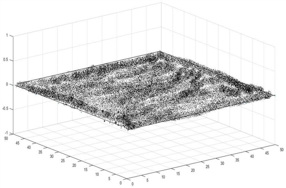
[0003] Through laser three-dimensional scanning of objects, collect point data as much as possible, but often due to some factors, the laser scanning beam is blocked by the object, resulting in incomplete collection of point cloud data, and cannot form an approximate closed state in space. At this time, most of them rely on technicians. According to the individual's understanding of the shape of the object, the point cloud is generated by drawing the third-party point cloud software in the three-dimensional space. Therefore, the existing technology is limited by the degree of technical personnel's understanding of the characteristics of the target object and the degree of mastery of the software. Human error is large, the obtained data is not objective enough, and the drawing cycle is long

Method used


Image

  • Compensation algorithm for three-dimensional space measurement result data
  • Compensation algorithm for three-dimensional space measurement result data
  • Compensation algorithm for three-dimensional space measurement result data

Examples


Embodiment Construction

[0034] The following will clearly and completely describe the technical solutions in the embodiments of the present invention with reference to the accompanying drawings in the embodiments of the present invention. Obviously, the described embodiments are only some, not all, embodiments of the present invention. All other embodiments obtained by persons of ordinary skill in the art based on the embodiments of the present invention belong to the protection scope of the present invention.

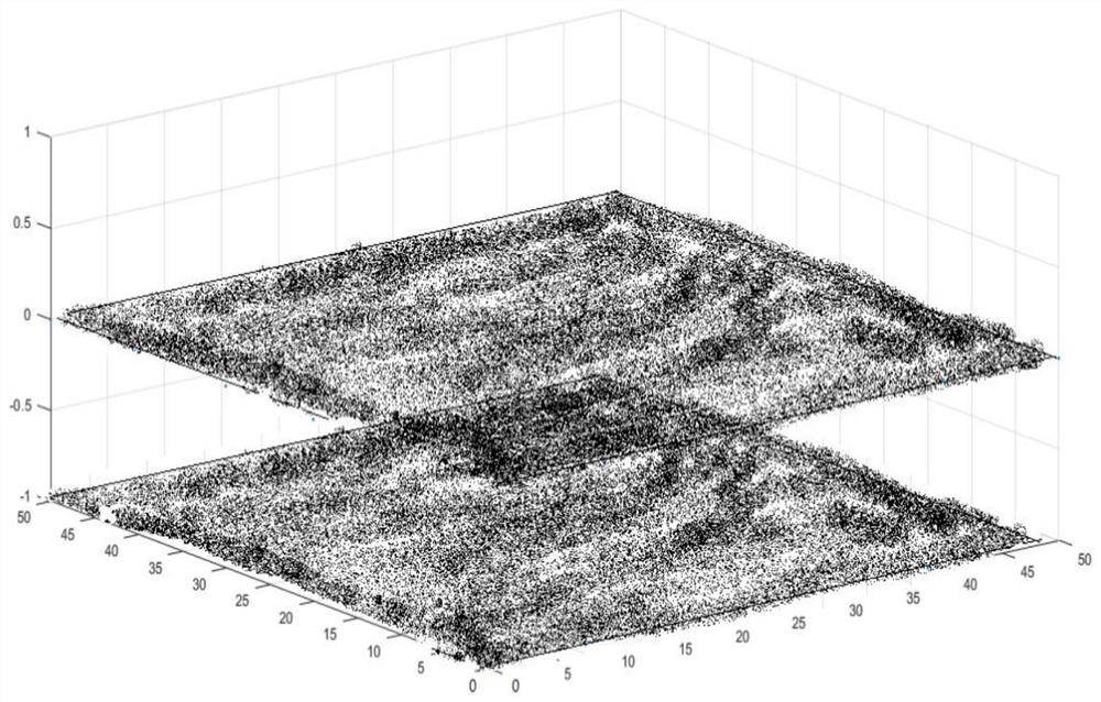
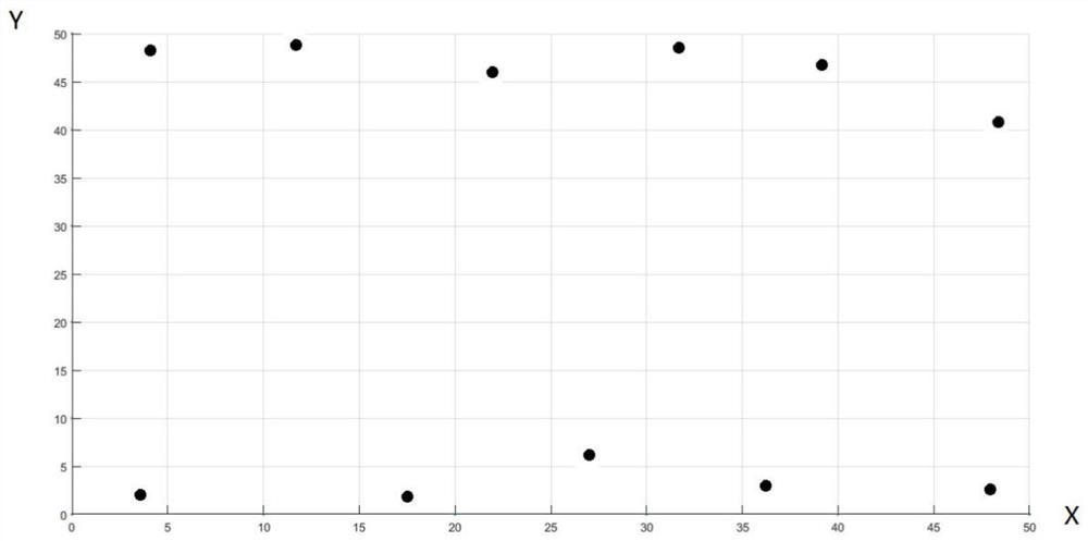
[0035] As shown in Figures 1-6, according to the compensation algorithm for three-dimensional space measurement result data described in the embodiment of the present invention, the algorithm includes the following steps:

[0036] Step 1, acquisition of point cloud data;

[0037] Step 2, compensate the point cloud of the bottom surface of the object;

[0038] Step 3, compensate the point cloud around the object;

[0039] In a specific embodiment of the present invention, in the step of obta...


PUM


Abstract

The invention discloses a compensation algorithm for three-dimensional space measurement result data, and the algorithm comprises the steps: obtaining point cloud data: scanning an exposed surface ofan object through employing laser radar equipment, obtaining initial data, and converting the initial data through employing a trigonometric function to obtain rectangular coordinate system data; compensating the bottom point cloud of the object, processing the coordinates by using algorithm software based on the obtained original point cloud coordinates, and keeping the coordinate values of the original point cloud unchanged to obtain bottom point cloud data; compensating point clouds around the object, finding out a difference value between a minimum value coordinate and a maximum value coordinate in the point clouds through a comparison algorithm according to bottom surface point cloud data, and screening out projection area edge points of the minimum value and the maximum value of eachsection through the comparison algorithm. The invention has the technical effects that the missing surface point cloud is calculated through feature compensation of the surface of the target object,manual compensation errors are reduced, the point cloud of the missing surface is compensated according to the feature density of the target object, and approximately closed complete point cloud dataof the target object is obtained.

Description

technical field [0001] The invention relates to the technical field of three-dimensional space data processing, in particular to a compensation algorithm for three-dimensional space measurement result data. Background technique [0002] Using modern optical frequency band technology to transmit and control electromagnetic waves in the measured area is the main working principle of lidar mapping technology. Through the transmission and collection of electromagnetic waves, it is possible to accurately measure the height, distance and volume of objects. Compared with ordinary light waves, laser has the characteristics of obvious directionality, pure color, outstanding coherence, and strong anti-interference ability. Therefore, the use of laser and engineering surveying and mapping can achieve ideal results. During work, the laser beam hits the surface of the object to produce a reflection effect, and the reflected beam is received by the radar. The internal system of the radar ...

Claims


Application Information

Patent Timeline
IPC IPC(8): G06T5/00G06T7/13G06T7/62
CPCG06T7/13G06T7/62G06T2207/10028G06T2207/10044G06T5/77
Inventor 徐莹
Owner 富德康(北京)科技股份有限公司
Learn More