
Long-service-life power electrical transformer

A technology for electric power and transformers, applied in the field of transformers, can solve the problems of high manufacturing cost, reduced service life of transformers, damage to cooling systems, etc., and achieves the effects of simple rotation adjustment structure, extended service life and convenient operation.

Active Publication Date: 2020-10-30
鑫大变压器有限公司
View PDF10 Cites 8 Cited by
  • Summary
  • Abstract
  • Description
  • Claims
  • Application Information

AI Technical Summary

Problems solved by technology

Transformer oil tank and cooling system, the manufacturing cost is getting higher and higher, and the technology is getting more and more complicated
[0005] Therefore, once the transformer is put into use, due to wind, sun, rain, etc., the structure of the oil tank and the heat dissipation pipe on the outer wall is prone to corrosion. Once rust occurs, the entire cooling system will be damaged very quickly, especially if the transformer is installed on It is very difficult to repair and replace the high places such as utility poles that are not easy to repair at this time, and the service life of the transformer is also greatly reduced.

Method used


Image

  • Long-service-life power electrical transformer
  • Long-service-life power electrical transformer
  • Long-service-life power electrical transformer

Examples


Embodiment Construction

[0038] The implementation mode of the present invention is illustrated by specific specific examples below, and those who are familiar with this technology can easily understand other advantages and effects of the present invention from the contents disclosed in this description. Obviously, the described embodiments are a part of the present invention. , but not all examples. Based on the embodiments of the present invention, all other embodiments obtained by persons of ordinary skill in the art without making creative efforts belong to the protection scope of the present invention.

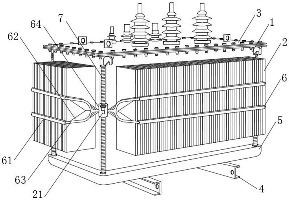
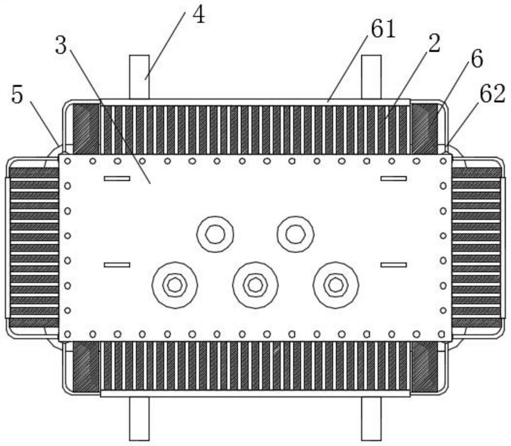
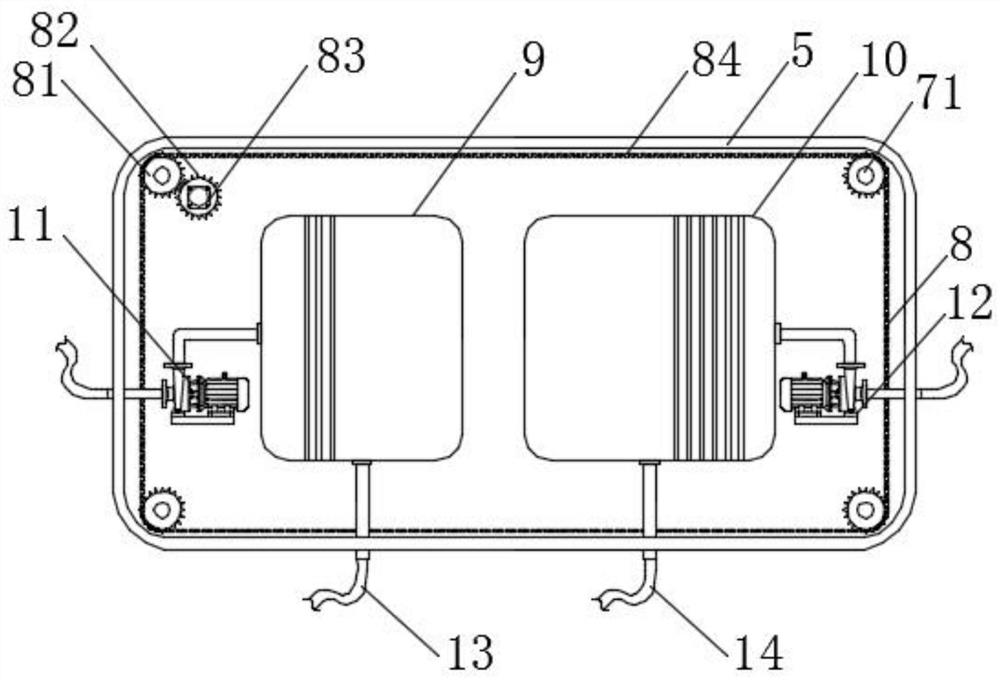
[0039] Refer to the attached Figure 1-3 and Figure 7 , a long service life power electrical transformer in this embodiment, comprising a fuel tank 1, a cooling plate group 2, a top cover 3 and an installation angle steel 4, the cooling plate group 2 is fixedly arranged on the outer wall of the fuel tank 1 and communicated with the fuel tank 1, The top cover 3 is arranged on the top of the fue...


PUM


Abstract

The invention discloses a power electrical transformer with long service life and particularly relates to the field of transformers. The transformer comprises an oil tank, a heat dissipation plate group, a top cover and mounting angle steel, wherein the heat dissipation plate group is fixedly arranged on an outer wall of the oil tank and communicates with the oil tank, the top cover is arranged atthe top of the oil tank and an edge is fixedly connected with the oil tank through screws, the mounting angle steel is arranged at the bottom of the oil tank, a driving box is fixedly arranged between the oil tank and the mounting angle steel, a rust-proof cleaning assembly is arranged in each heat dissipation plate group, and a lifting mechanism is fixedly arranged at the top of the driving boxcorresponding to the position between every two adjacent heat dissipation plate groups. According to the transformer, the rust-proof cleaning assembly is arranged in each heat dissipation plate group,a rust-proof cleaning system is used in cooperation with the lifting mechanism, the heat dissipation plates can be cleaned at ordinary times, when the rust-proof layers on the outer walls of the oiltank and the heat dissipation plates are about to be damaged, rust-proof oil is sprayed to the outer walls of the oil tank and the heat dissipation plates, the whole rust-proof cleaning system can prevent a cooling system from being damaged, and the service life of the whole transformer is prolonged.

Description

technical field [0001] The embodiments of the present invention relate to the field of transformers, and in particular to a power transformer with long service life. Background technique [0002] The transformer is a device that uses the principle of electromagnetic induction to change the AC voltage. The main components are the primary coil, the secondary coil and the iron core (magnetic core). The main functions are: voltage conversion, current conversion, impedance conversion, isolation, voltage stabilization (magnetic saturation transformer), etc. [0003] The transformer will generate a lot of heat when it is working, especially in the peak period of electricity consumption, such as at noon in summer, most people use air conditioners to cool down, and the power consumption of air conditioners is large. The main transformer is often in supersaturated long-term operation. After long-term super-saturated operation, the temperature is extremely high, causing the main trans...

Claims


Application Information

Patent Timeline
IPC IPC(8): H01F27/02H01F27/06H01F27/08H01F27/14H01F27/22H01F27/23B08B1/00B08B3/02B08B13/00
CPCH01F27/025H01F27/06H01F27/08H01F27/14H01F27/22H01F27/23B08B3/02B08B13/00B08B1/12B08B1/30
Inventor 不公告发明人
Owner 鑫大变压器有限公司
Learn More