
COB die bonder

A die-bonding machine and die-bonding technology, which is applied in the manufacture of electric solid-state devices, conveyor objects, semiconductor/solid-state devices, etc., can solve the problems of difficulty in meeting process requirements, low die-bonding efficiency, etc. The effect of improving the solidification efficiency

Pending Publication Date: 2020-10-30
SHEN ZHEN TALUER TECH CO LTD
View PDF0 Cites 2 Cited by
  • Summary
  • Abstract
  • Description
  • Claims
  • Application Information

AI Technical Summary

Problems solved by technology

As the size of LED wafers becomes smaller, the number of lamp beads in the same PCB area increases, and the die bonding needs to be completed as soon as possible after brushing the solder paste. However, the existing die bonding devices either have low die bonding efficiency or double swing arms. It is difficult to meet the process requirements of the above-mentioned veneer for the dual solid crystal table

Method used


Image

  • COB die bonder

Examples


Embodiment Construction

[0013] The present invention will be further described below in conjunction with the description of the drawings and specific embodiments.

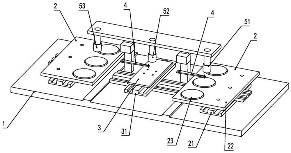
[0014] Such as figure 1 As shown, a COB crystal bonding machine includes a base 1, a crystal bonding table 3, a wafer transfer mechanism 2 and a swing arm 4, and the crystal bonding table 3 and the wafer transfer mechanism 2 are respectively arranged on the support 1, there are two wafer transfer mechanisms 2 located on both sides of the die-bonding table 3, and two swing arms 4 are located on the die-bonding table 3 and the wafer transfer mechanism respectively. 2, one end of the swing arm 4 is a rotating end, and the other end is a wafer grabbing end, and the rotating end of each swing arm 4 is connected to a swing arm driving motor and a Z-axis motor correspondingly, so The swing arm drive motor drives the wafer grabbing end of the swing arm 4 to reciprocate between the wafer transfer mechanism 2 and the solid crystal table 3

[0015...


PUM


Abstract

The invention provides a COB die bonder. The die bonder comprises a support, a die bonding table, wafer disc conveying mechanisms and swing arms, wherein the die bonding table and the wafer disc conveying mechanisms are respectively arranged on the support, the two wafer disc conveying mechanisms are respectively positioned on two sides of the die bonding table, the two swing arms are respectivelypositioned between the die bonding table and the wafer disc conveying mechanisms, the swing arms are provided with Z-axis motors of which the position can be adjusted up and down, one end of each swing arm is a rotating end, the other end of each swing arm is a wafer grabbing and fixing end, the rotating end of each swing arm is correspondingly connected with a swing arm driving motor, and the swing arm driving motors drive the wafer grabbing ends of the swing arms to reciprocate between the wafer disc conveying mechanisms and the wafer fixing table. The die bonding table is advantaged in that the two swing arms are matched with the two wafer disc conveying mechanisms to carry out die bonding on the die bonding table together so that the die bonding production takt is improved, and die bonding efficiency is improved.

Description

technical field [0001] The invention relates to a crystal bonder, in particular to a COB crystal bonder. Background technique [0002] COB technology is an emerging LED packaging technology, which is different from the traditional SMD positive packaging technology. It is a flip-chip technology that directly solders the light-emitting chip to the PCB. As the size of LED wafers becomes smaller, the number of lamp beads in the same PCB area increases, and the die bonding needs to be completed as soon as possible after brushing the solder paste. However, the existing die bonding devices either have low die bonding efficiency or double swing arms. It is difficult to meet the process requirements of the above-mentioned veneer for the dual die-bonding station. Contents of the invention [0003] In order to solve the problems in the prior art, the present invention provides a COB crystal bonding machine with high crystal bonding efficiency. [0004] The present invention provide...

Claims


Application Information

Patent Timeline
Patent Type & Authority Applications(China)
IPC IPC(8): H01L21/677H01L21/67H01L25/075H01L33/48
CPCH01L21/677H01L21/67144H01L21/67121H01L25/0753H01L33/48
Inventor 曾逸刘耀金谢启全
Owner SHEN ZHEN TALUER TECH CO LTD
Learn More