
Pin guiding, conveying and crimping device

A technology for welding devices and pins, which is applied in the direction of connection, electrical components, circuits, etc., and can solve problems such as poor soldering reliability of terminal terminals, falling off conductivity, etc.

Active Publication Date: 2020-10-30
ANHUI LANRUI ELECTRONICS TECH
View PDF12 Cites 0 Cited by
  • Summary
  • Abstract
  • Description
  • Claims
  • Application Information

AI Technical Summary

Problems solved by technology

[0002] When welding LED lamp bead wires, soldering is often used for welding. In the prior art, when conducting wire welding to LED lamp beads, because the LED lamp bead itself is small, the operator holds the The two pins of the wire, so that the pins are against the two terminals of the LED lamp bead, and the soldering gun is held in hand, and the welding head of the soldering gun sticks a little molten tin liquid, so as to realize the two wiring between the pins and the LED Welding of terminals, the efficiency of the above-mentioned processing and production of LED lamp beads is very low, and the welding reliability between the lead wire and the two terminals of the LED is not good, which is easy to cause problems of falling off and poor conductivity

Method used


Image

  • Pin guiding, conveying and crimping device
  • Pin guiding, conveying and crimping device
  • Pin guiding, conveying and crimping device

Examples


Embodiment Construction

[0025] In order to make the objects and advantages of the present invention clearer, the present invention will be described in detail below in conjunction with the examples. It should be understood that the following words are only used to describe one or several specific implementation modes of the present invention, and do not strictly limit the protection scope of the specific claims of the present invention. As used herein, the terms "parallel" and "perpendicular" are not limited to their strict geometric definitions, but include reasonable and inconsistent tolerances for machining or human error;

[0026] The following is a detailed description of the pin guide crimping device of the present invention in conjunction with the entire array type LED lamp bead wire welding system:

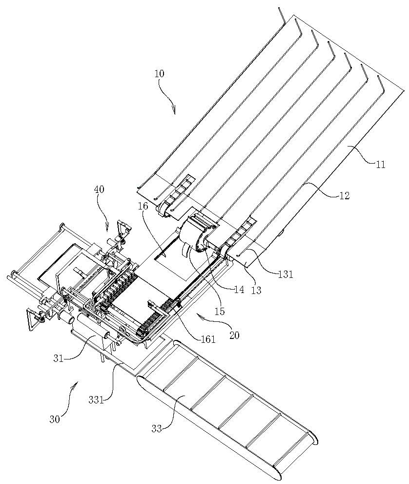
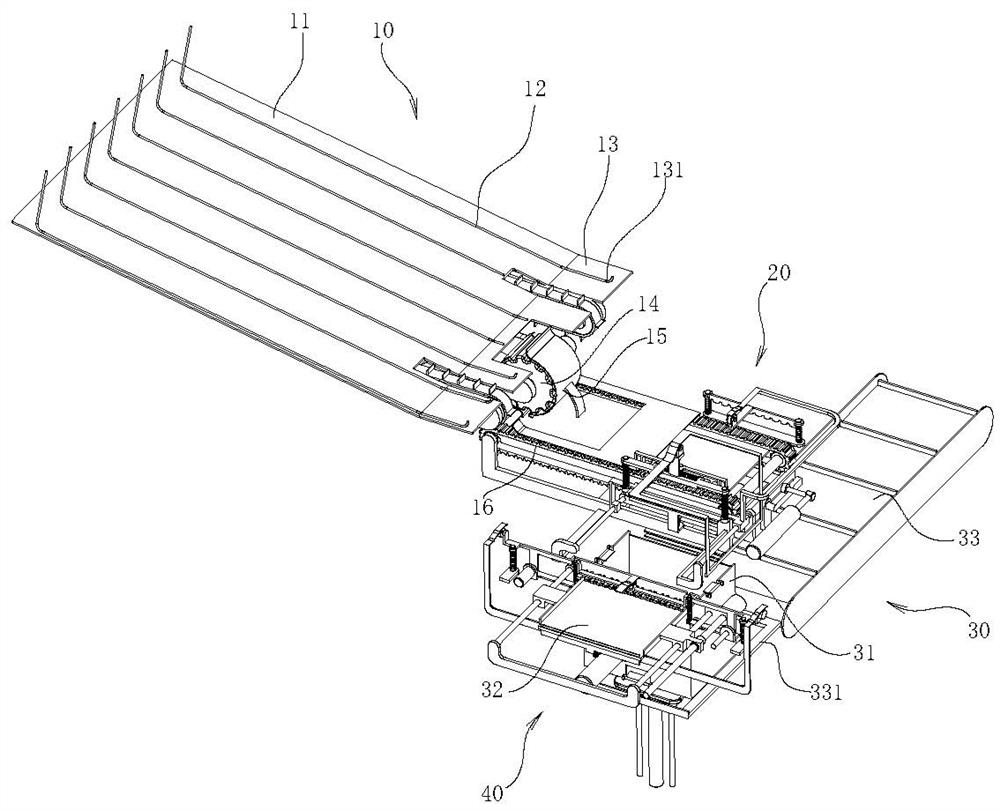
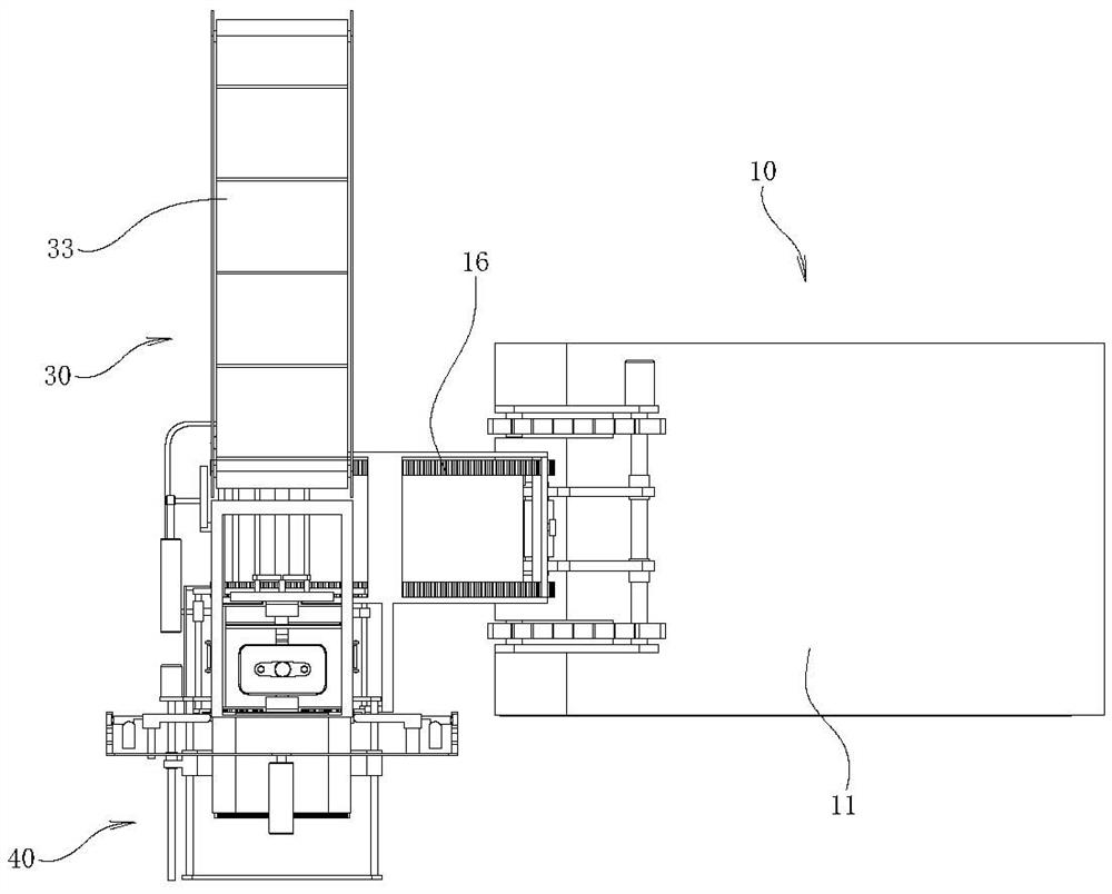
[0027] Attached below Figure 1 to Figure 27 , the array type LED lamp bead wire welding system of the present invention is described in detail:

[0028] An array type LED lamp bead wire weldin...


PUM


Abstract

The invention relates to a pin guiding, conveying and crimping device. A pin welding device is arranged beside the pin guiding, conveying and crimping device; the pin welding device is used for welding wire pins to wiring terminals of the array type LED lamp beads. The pin guiding, conveying and crimping device comprises a crimping head arranged above a translation table of the feeding device of the array type LED lamp beads; the crimping head is provided with a clamping comb plate used for clamping two pins of a wire harness. The clamping comb plate moves horizontally and straightens the twopins of the wire harness. Before the two wiring pins are welded with the wiring terminals of the LED lamp bead on the translation table, the clamping comb plate on the crimping head is in contact withthe two connecting wires; and the clamping comb plate is driven to move horizontally, so that the positions of the two wiring pins are further limited, the two pins of the wiring harness are just located over the wiring terminals of the LED lamp beads, the pin welding device is started, and welding operation of the two pins and the wiring terminals of the LED lamp beads is implemented.

Description

technical field [0001] The invention relates to the technical field of LED lamp intelligent manufacturing, in particular to a pin guiding and crimping device. Background technique [0002] When welding LED lamp bead wires, soldering is often used for welding. In the prior art, when conducting wire welding to LED lamp beads, because the LED lamp bead itself is small, the operator holds the The two pins of the wire, so that the pins are against the two terminals of the LED lamp bead, and the soldering gun is held in hand, and the welding head of the soldering gun sticks a little molten tin liquid, so as to realize the two wiring between the pins and the LED The soldering of the terminals, the above-mentioned processing and production of the LED lamp bead is very inefficient, and the soldering reliability of the lead wire and the two terminals of the LED is not good, which is easy to cause problems of falling off and poor conductivity. Contents of the invention [0003] The ...

Claims


Application Information

Patent Timeline
Patent Type & Authority Applications(China)
IPC IPC(8): H01R43/055H01R43/02
CPCH01R43/0263H01R43/055
Inventor 储昭学胡广储根传胡力
Owner ANHUI LANRUI ELECTRONICS TECH
Learn More