Faucet handle welding equipment and working method thereof

A technology for welding equipment and faucets, which is applied in the field of faucets, can solve the problems of time-consuming and laborious production efficiency, and cannot meet the production needs of faucets, and achieve the effects of increased production speed, time-saving and labor-saving operation steps, and convenient production operations

Pending Publication Date: 2021-01-05
鹤山市正鑫卫浴科技有限公司
View PDF0 Cites 0 Cited by
  • Summary
  • Abstract
  • Description
  • Claims
  • Application Information

AI Technical Summary

Problems solved by technology

[0003] The faucet handle is an indispensable part of the faucet. It is generally made of a handle plate and a handle core set at one end of the handle plate. The rotary switch is connected; the faucet handles on the existing market are all manually welded during production, which is time-consuming and laborious, and the production efficiency is low, which cannot meet the production needs of the faucet. It is necessary to improve it

Method used


Image

  • Faucet handle welding equipment and working method thereof
  • Faucet handle welding equipment and working method thereof
  • Faucet handle welding equipment and working method thereof

Examples


Embodiment Construction

[0029] The following will clearly and completely describe the technical solutions in the embodiments of the present invention with reference to the accompanying drawings in the embodiments of the present invention. Obviously, the described embodiments are only some, not all, embodiments of the present invention. Based on the embodiments of the present invention, all other embodiments obtained by persons of ordinary skill in the art without creative work, any modifications, equivalent replacements, improvements, etc., shall be included in the protection scope of the present invention Inside.

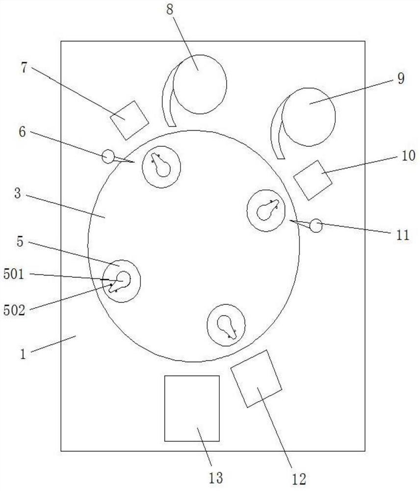
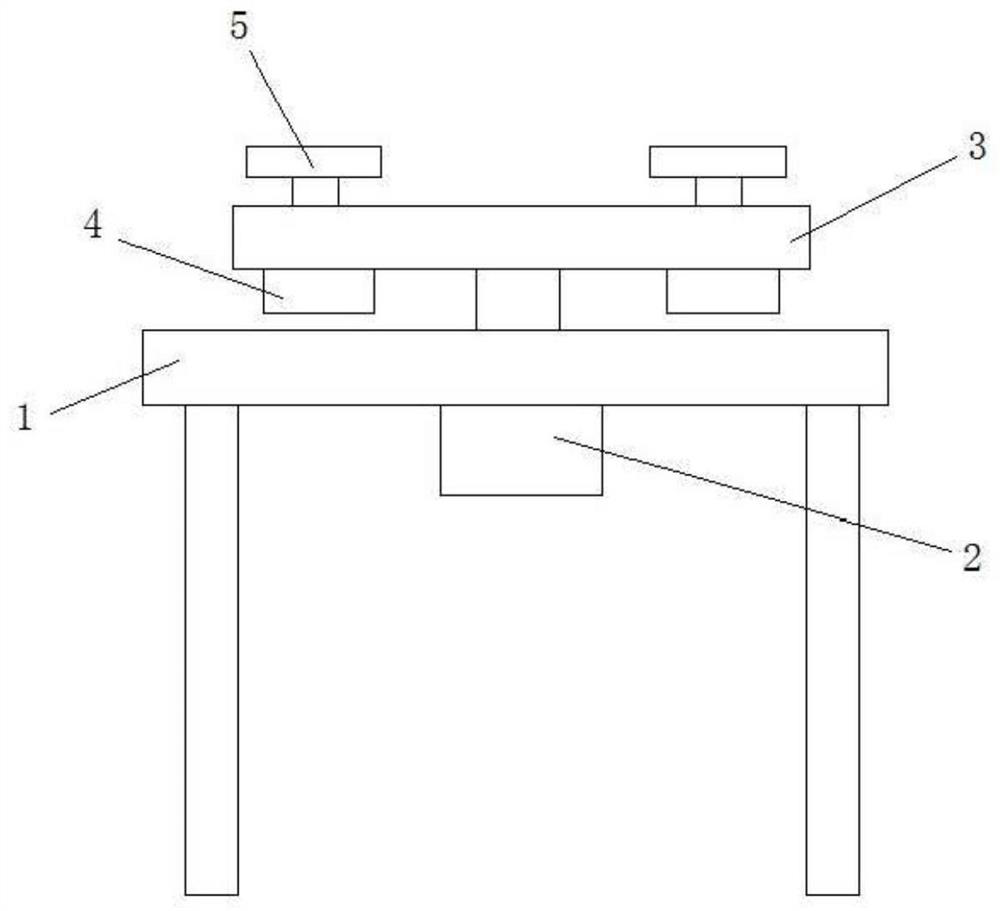
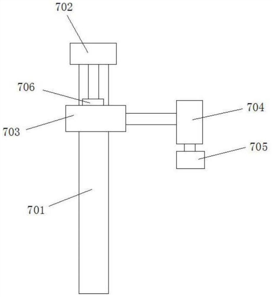
[0030] Such as Figure 1 to Figure 4 As shown, the faucet handle welding equipment in this embodiment includes a workbench 1, a rotating motor 2, and a turntable 3; It is fixedly connected with the center position of the turntable 3, and four station assemblies are arranged at equal intervals on the turntable 3; The output shaft of the bit motor 4 passes through the turntable 3 and is f...


PUM


Abstract

The invention discloses faucet handle welding equipment and a working method thereof. The faucet handle welding equipment comprises a workbench, a rotary motor and a rotary table. The rotary motor isconnected to the workbench, an output shaft of the rotary motor is connected with the rotary table, and four station assemblies are arranged on the rotary table. A first machining assembly, a second machining assembly and a material receiving assembly are arranged on the outer side of the rotary table. The working method comprises the following steps: S1, a handle plate is manually placed in a placing groove; S2, a placing table is controlled to rotate to the position of the first machining assembly; S3, a first clamping mechanism takes a handle core and places the handle core on the handle plate; S4, a first laser welding machine carries out welding operation; S5, the placing table is rotated to the position of the second machining assembly; S6, a second clamping mechanism takes a handlering and places the handle ring on the handle plate; S7, a second laser welding machine performs welding operation; S8, the placing table is rotated to the position of the material receiving assembly;and S9, a third clamping mechanism takes out a faucet finished product.

Description

technical field [0001] The invention relates to the field of faucets, in particular to a faucet handle welding device and a working method thereof. Background technique [0002] Water tap is the popular title of water valve, which is used to control the size switch of water flow and has the effect of saving water. The replacement speed of the faucet is very fast, from the old-fashioned cast iron process to the electroplating knob type, and then to the stainless steel single temperature single control faucet, the stainless steel dual temperature dual control faucet, and the kitchen semi-automatic faucet. Now, more and more consumers are choosing faucets, and they will comprehensively consider materials, functions, shapes and other aspects. [0003] The faucet handle is an indispensable part of the faucet. It is generally made of a handle plate and a handle core set at one end of the handle plate. The rotary switch is connected; the faucet handles on the existing market are ...

Claims


Application Information

Patent Timeline
IPC IPC(8): B23K26/21B23K26/16B23K26/70
CPCB23K26/16B23K26/21B23K26/702
Inventor 陈一鑫
Owner 鹤山市正鑫卫浴科技有限公司
Why Eureka
Try Eureka