

Batching stirrer
A mixer and agitator shaft technology, which is applied to mixer accessories, mixers with rotating agitation devices, mixers, etc., can solve the problems of environmental protection testing not up to standard, affecting production operations, and reducing mixing efficiency, so as to facilitate production operations and observation , Ease of production operation, and the effect of environmental protection testing up to the standard
- Summary
- Abstract
- Description
- Claims
- Application Information
AI Technical Summary
Problems solved by technology
Method used
Image

Examples
Embodiment 1
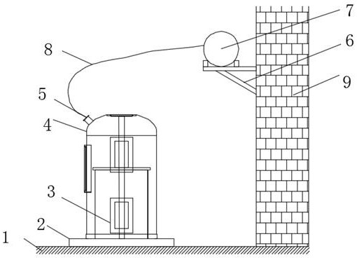
[0032] Such as Figure 1-6 As shown, a batching mixer includes a ground 1 and a wall 9 arranged on the ground 1,
[0033] The top of the ground 1 is provided with a receiving plate 2, and the top of the receiving plate 2 is placed with a casing 3, and the outer casing of the casing 3 is provided with a gas collecting hood 4, and the gas collecting hood 4 is provided with an air outlet 5;
[0034] The side wall of the wall 9 is provided with a receiving plate 6, and the top of the receiving plate 6 is fixedly installed with a waste gas collection main pipe 7, and the waste gas collection main pipe 7 and the air outlet 5 are connected through a waste gas collection hose 8;
[0035] The housing 3 is provided with a stirring mechanism.
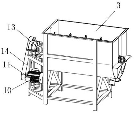
[0036] The stirring mechanism includes a servo motor 10, the servo motor 10 is installed on the outer wall of the housing 3, the output end of the servo motor 10 is connected with a driving gear 11, and a stirring shaft 12 is arranged to rotate i...
Embodiment 2
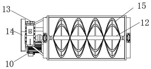
[0039] Such as Figure 1-6 As shown, the stirring mechanism includes a servo motor 10, the servo motor 10 is installed on the outer wall of the housing 3, the output end of the servo motor 10 is connected with a driving gear 11, and a stirring shaft 12 is arranged to rotate in the housing 3, and one end of the stirring shaft 12 protrudes The casing 3 is provided with a driven gear 13, the driving gear 11 is connected to the driven gear 13 through a conveyor belt 14, and the stirring shaft 12 is provided with a plurality of pairs of symmetrically arranged elastic stirring blades 15.
[0040] The stirring shaft 12 is symmetrically provided with two bearings 16, the two bearings 16 are provided with a rotating rod 17, and the stirring shaft 12 is also symmetrically provided with two internal gears 18, and the two internal gears 18 are located between the two bearings 16. Two external gears 19 are arranged symmetrically on the outside of the rotary rod 17, and the two external gea...
Embodiment 3
[0045] Such as Figure 1-6 As shown, the top of the receiving plate 2 is centered on the mixer body 3 with an annular groove 24, the gas collecting cover 4 is placed in the annular groove 24, and two arc-shaped splints 25 are symmetrically arranged in the annular groove 24, and the two arc-shaped splints 25 is slidingly arranged in the annular groove 24, and the two arc-shaped splints 25 are used to clamp the gas collecting cover 4, and the two side walls of the receiving plate 2 are provided with strip-shaped holes 26 symmetrically along the horizontal axis direction, and the two strip-shaped holes 26 are Connected with the annular groove 24, a pull rod 27 is slidably arranged in the strip hole 26, and one end of the pull rod 27 near the arc splint 11 extends into the annular groove 24 and is connected with the arc splint 25, and the pull rod 27 is provided with a first spring 28 , the first spring 28 is located in the bar-shaped hole 26 .
[0046] By setting the annular gro...
PUM
 Abstract
Description
Claims
Application Information