Multi-target telemetry ground station digital acquisition method, receiving method and device

A technology of digital acquisition and receiving method, which is applied in the field of communication and telemetry

Active Publication Date: 2020-10-30
CHENGDU FOURIER ELECTRONICS TECH +1
View PDF5 Cites 2 Cited by
  • Summary
  • Abstract
  • Description
  • Claims
  • Application Information

AI Technical Summary

Problems solved by technology

[0005] Aiming at the deficiencies and defects of the above-mentioned related prior art, the present invention provides a multi-target telemetry ground station digital acquisition method, receiving method and device, which greatly reduces the complexity of hardware design, and each sub-band has a separate AGC control The

Method used


Image

  • Multi-target telemetry ground station digital acquisition method, receiving method and device
  • Multi-target telemetry ground station digital acquisition method, receiving method and device
  • Multi-target telemetry ground station digital acquisition method, receiving method and device

Examples


Example Embodiment

[0073] Example 1

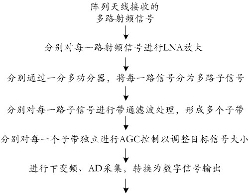
[0074] like figure 1 As shown, it is a flow chart of the multi-target telemetry ground station digital acquisition method in this example.

[0075] Step 1: performing LNA amplification on each channel of the multiple radio frequency signals received through the array antenna.

[0076] Step 2: Each amplified signal passes through a multiplexer to divide each signal into multiple sub-signals.

[0077] Step 3: performing band-pass filter processing on each channel of sub-signals respectively to form multiple sub-bands.

[0078] Step 4: According to the strength of the target signal in each different sub-band, AGC control is independently performed on each sub-band to adjust the size of the target signal.

[0079] Step 5: Perform down-conversion and AD acquisition on the signal adjusted by AGC, and convert it into a digital signal output.

[0080] Follow the steps above to complete the ground station digital acquisition for multi-target telemetry.

Example Embodiment

[0081] Example 2

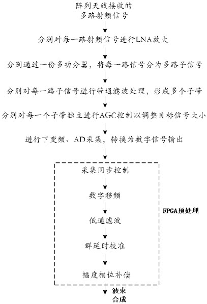
[0082] like figure 2 Shown is the preferred embodiment made on the basis of embodiment 1.

[0083] Step 1: performing LNA amplification on each channel of the multiple radio frequency signals received through the array antenna.

[0084] Step 2: Each amplified signal passes through a multiplexer to divide each signal into multiple sub-signals.

[0085] Step 3: performing band-pass filter processing on each channel of sub-signals respectively to form multiple sub-bands.

[0086] Step 4: According to the strength of the target signal in each different sub-band, AGC control is independently performed on each sub-band to adjust the size of the target signal.

[0087] Step 5: Perform down-conversion and AD acquisition on the signal adjusted by AGC, and convert it into a digital signal output.

[0088] Step 6: Preprocessing the digital signal through the FPGA for subsequent beam combining processing.

[0089] Wherein step 6 includes:

[0090] Step 6.1, acqui...

Example Embodiment

[0096] Example 3

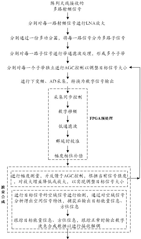
[0097] like image 3 As shown, it is a flow chart of the multi-target telemetry ground station receiving method provided in this example.

[0098] Step 1: performing LNA amplification on each channel of the multiple radio frequency signals received through the array antenna.

[0099] Step 2: Each amplified signal passes through a multiplexer to divide each signal into multiple sub-signals.

[0100] Step 3: performing band-pass filter processing on each channel of sub-signals respectively to form multiple sub-bands.

[0101] Step 4: According to the strength of the target signal in each different sub-band, AGC control is independently performed on each sub-band to adjust the size of the target signal.

[0102] Step 5: Perform down-conversion and AD acquisition on the signal adjusted by AGC, and convert it into a digital signal output.

[0103] Step 6: Preprocessing the digital signal through the FPGA for subsequent beam combining processing.

[0104] Amo...


PUM


Abstract

The invention discloses a multi-target telemetry ground station digital acquisition method, a multi-target telemetry ground station receiving method and a multi-target telemetry ground station digitalacquisition device. The multi-target telemetry ground station digital acquisition method comprises the following steps of: carrying out LNA amplification on each path of multiple paths of radio frequency signals received by an array antenna; dividing each path of signals into multiple paths of sub-signals through a one-to-many power divider; performing band-pass filtering processing on each pathof sub-signals to form a plurality of sub-bands; performing AGC control on each sub-band independently so as to adjust the size of a target signal; performing down-conversion and AD acquisition on thesignal which has been subjected to AGC adjustment so as to convert the signal into a digital signal, and outputting the digital signal, enabling an FPGA to preprocess the digital signal, outputting the preprocessed digital signal to a beam forming module through optical fibers to process the digital signal, then performing amplitude measurement, and feeding back the signal to AGC control, and performing airspace signal capture and tracking, and synthesizing synthesis signals for receiving and demodulation. According to the multi-target telemetry ground station digital acquisition method, themulti-target telemetry ground station receiving method and the multi-target telemetry ground station digital acquisition device method of the invention, hardware design complexity is greatly reduced;each sub-band is independently controlled by the AGC, meanwhile, the method is suitable for receiving different preemptive interruption signals, different targets do not interfere with each other, theproblem that large signals submerge small signals due to far and near field effects is solved, and multi-target signal receiving within the range of 1 km to 220 km is realized.

Description

technical field [0001] The invention belongs to the field of communication and telemetry, and relates to a multi-target telemetry ground station, in particular to a multi-target telemetry ground station digital acquisition method, receiving method and device. Background technique [0002] At present, the telemetry system can only achieve single-target telemetry, and the single-target telemetry system is far from meeting the telemetry needs of related fields in terms of flight tests, confrontation exercises, and weapon tests. The beam of the parabolic antenna system is relatively strong, and the tracking method adopts the characteristics of mechanical tracking, so that the parabolic antenna system can only receive one target signal at the same time. Limited by the physical characteristics of mechanical tracking, it is impossible to track multiple targets simultaneously with a parabolic antenna. [0003] In order to meet the requirements of the telemetry link gain index and i...

Claims


Application Information

Patent Timeline
IPC IPC(8): H04Q9/00H04Q9/04H04J3/06H04B7/06G08C17/02G08C23/06
CPCH04Q9/00H04Q9/04H04J3/0638H04B7/0617G08C17/02G08C23/06H04Q2209/20H04Q2209/40
Inventor 彭彬
Owner CHENGDU FOURIER ELECTRONICS TECH
Why Eureka
Try Eureka