
Spraying device for preventing liquid from adhering to pipe walls for long time

A technology of spraying device and pipe wall, which is applied in the field of spraying device to avoid long-term adhesion of liquid to the pipe wall, can solve the problems of fixed spraying angle, accumulation blockage, time-consuming and labor-intensive, etc., and achieve the effect of avoiding corrosion or accumulation blockage.

Inactive Publication Date: 2020-11-03
SHAOXING FANGDAN TECH CO LTD
View PDF0 Cites 4 Cited by
  • Summary
  • Abstract
  • Description
  • Claims
  • Application Information

AI Technical Summary

Problems solved by technology

[0003] The infusion tube of the injection device at the present stage will not be automatically cleaned in time after use, and the liquid residue will adhere to the inner wall of the tube, which will cause the tube wall to corrode or accumulate and block, so that the injection cannot be carried out smoothly, and when the type of injection liquid is different, the liquid needs to be replaced manually The type of supply also needs to be replenished by adding liquid manually, which is inefficient and time-consuming, and the spray angle is fixed and cannot be adjusted freely

Method used


Image

  • Spraying device for preventing liquid from adhering to pipe walls for long time
  • Spraying device for preventing liquid from adhering to pipe walls for long time
  • Spraying device for preventing liquid from adhering to pipe walls for long time

Examples


Embodiment Construction

[0017] All features disclosed in this specification, or steps in all methods or processes disclosed, may be combined in any manner, except for mutually exclusive features and / or steps.

[0018] Combine below Figure 1-5 The present invention is described in detail, and for convenience of description, the orientations mentioned below are now stipulated as follows: figure 1 The up, down, left, right, front and back directions of the projection relationship itself are the same.

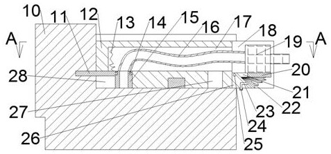
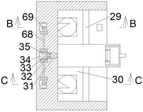
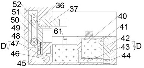
[0019] A spraying device for avoiding long-term adhesion of liquid to the pipe wall of the device of the present invention includes a box body 10. The top surface of the box body 10 is provided with an electric slider chute 30 with an opening to the left, and the bottom surface of the electric slider chute 30 is An electric guide rail 29 is fixedly arranged, and the electric guide rail 29 is connected to the electric slide block 12 by power sliding. The right end of the electric slide block 12 is provid...


PUM


Abstract

The invention discloses a spraying device for preventing liquid from adhering to pipe walls for a long time. The spraying device comprises a box body, an electric sliding block sliding groove with a leftward opening is formed in the top surface of the box body, an electric guide rail is fixedly arranged on the bottom surface of the electric sliding block sliding groove, and the electric guide railis in power sliding connection with an electric sliding block; the right end of the electric sliding block is provided with an angle adjusting groove which is through up and down and provided with aleftward opening, and the left end wall of the bottom end of the angle adjusting groove is fixedly provided with a slope supporting block, the bottom end of the slope supporting block is fixedly provided with a rotating plate shaft, and the front and rear ends of the rotating plate shaft are rotatably connected with the left end of a rotating supporting plate; and an angle adjusting air bag is fixedly connected between the bottom face of the rotating supporting plate and a top end slope of the slope supporting block, a spraying head device is fixedly arranged on the top face of the rotating supporting plate, and two inclined block sliding grooves with rightward openings are formed in the left end wall of the electric sliding block sliding groove in a front-back symmetry manner. Residual liquid in a used infusion tube can be automatically collected in time through the pressure difference, and the spraying angle can be freely adjusted.

Description

technical field [0001] The invention relates to the related technical field of spraying or atomizing devices, in particular to a spraying device that prevents liquid from adhering to pipe walls for a long time. Background technique [0002] The injection device is a vacuum acquisition device that uses fluid to transfer energy and quality. It uses a water flow with a certain pressure to spray out through nozzles that are symmetrically arranged with a certain side slope and converge on a focal point. Due to the extremely high flow rate of the jet water, the pressure energy is converted into velocity energy, and the pressure in the suction area is reduced to generate a vacuum. [0003] The infusion tube of the injection device at the present stage will not be automatically cleaned in time after use, and the liquid residue will adhere to the inner wall of the tube, which will cause the tube wall to corrode or accumulate and block, so that the injection cannot be carried out smoo...

Claims


Application Information

Patent Timeline
Patent Type & Authority Applications(China)
IPC IPC(8): B05B15/50B05B14/00B05B9/04B05B15/68
CPCB05B9/04B05B14/00B05B15/50B05B15/68
Inventor 郑美玲
Owner SHAOXING FANGDAN TECH CO LTD
Learn More