Apparatus using an electro-catalytic coating to reduce ship's friction and prevent biofouling

an electrocatalytic coating and apparatus technology, applied in the field of layered coatings and apparatuses, can solve the problems of significantly reducing the attachment of marine creatures by electrical current along the coating, and achieve the effects of reducing friction, preventing biofouling, and reducing the frictional resistance of sailing

Inactive Publication Date: 2014-11-13
WU KEE RONG +5
View PDF5 Cites 18 Cited by
  • Summary
  • Abstract
  • Description
  • Claims
  • Application Information

AI Technical Summary

Benefits of technology

[0007]The invention provides an apparatus and a layered coating, preferably by electric arc spraying technique, for the generation of electro-catalytic gases to reduce friction and to prevent biofouling for a submerged structure such as a ship. The apparatus consists of an anodic layer and a cathodic layer, which are electrically separated and coated on the outer surface of the submerged hull of a ship or an underwater structure. A DC power supply unit is connected to the layers. The anodic layer, the cathodic layer, the DC power supply unit and the surrounding seawater form a conducting path for the electro-catalytic evolution of hydrogen and oxygen gases. Contrary to other known micro-bubble friction reduction methods, the evolved gases form a thin gas film, or a hydrophobic surface, on the submerged hull, and the frictional resistance of sailing is reduced. In addition, the electric current along the coating significantly reduces the attachment of marine creatures, such as barnacles, algae, seaweeds, weeds, carssostrea gigas, hydroids, and bivalves to the outer surface of the submerged hull sailing at speeds below five knots, which is the range of speeds marine creatures can reside.

Problems solved by technology

In addition, the electric current along the coating significantly reduces the attachment of marine creatures, such as barnacles, algae, seaweeds, weeds, carssostrea gigas, hydroids, and bivalves to the outer surface of the submerged hull sailing at speeds below five knots, which is the range of speeds marine creatures can reside.

Method used


Image

  • Apparatus using an electro-catalytic coating to reduce ship's friction and prevent biofouling
  • Apparatus using an electro-catalytic coating to reduce ship's friction and prevent biofouling
  • Apparatus using an electro-catalytic coating to reduce ship's friction and prevent biofouling

Examples


Embodiment Construction

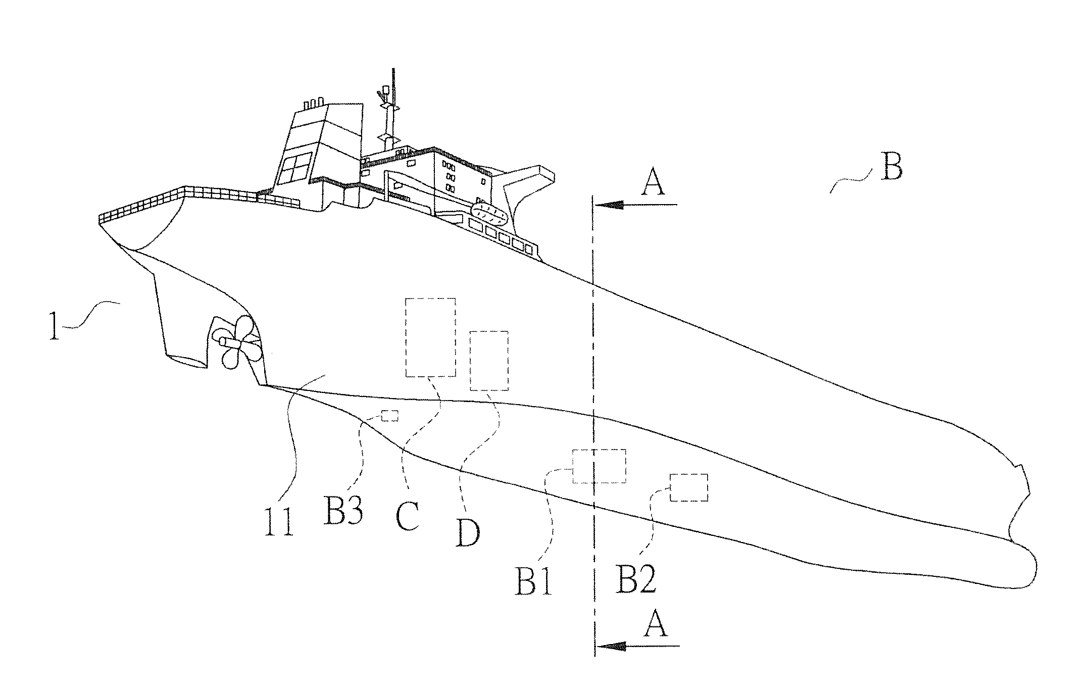
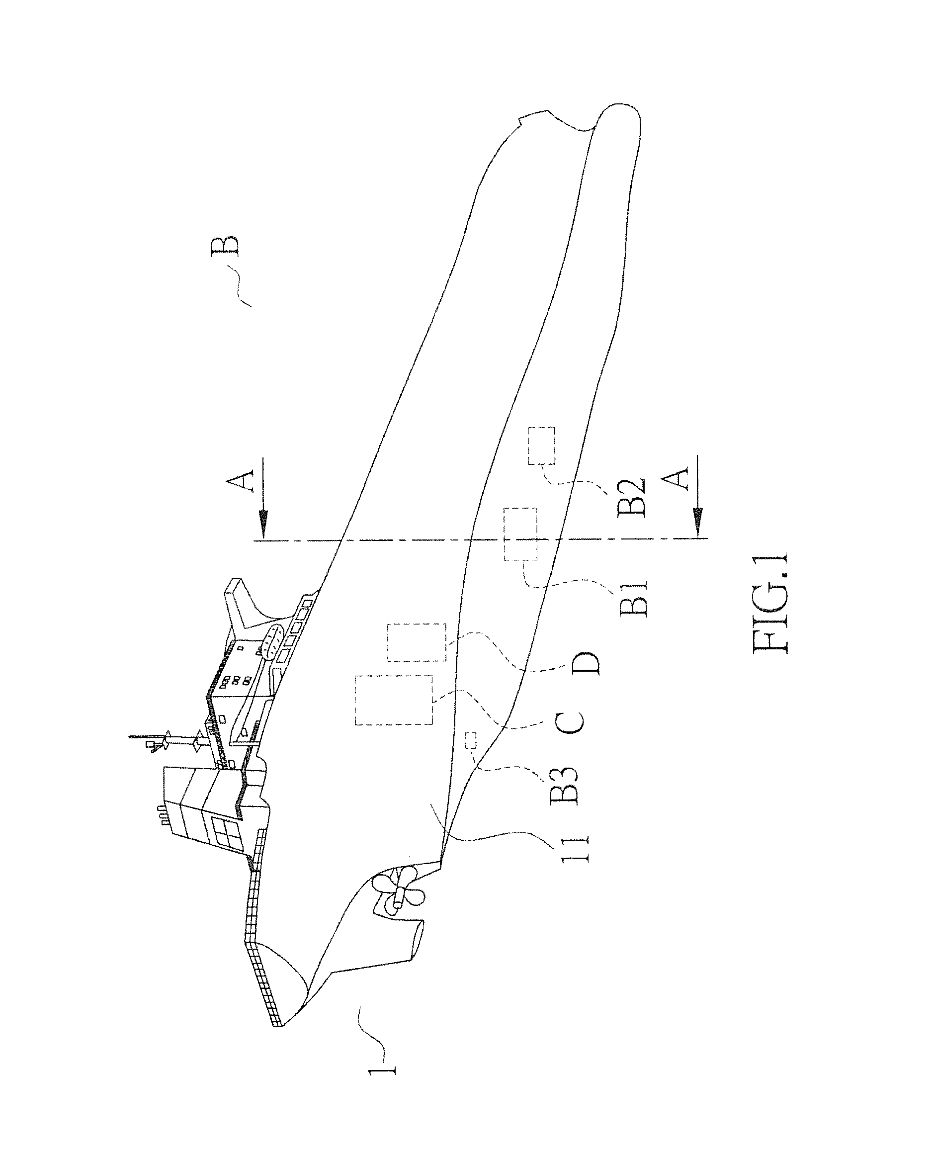
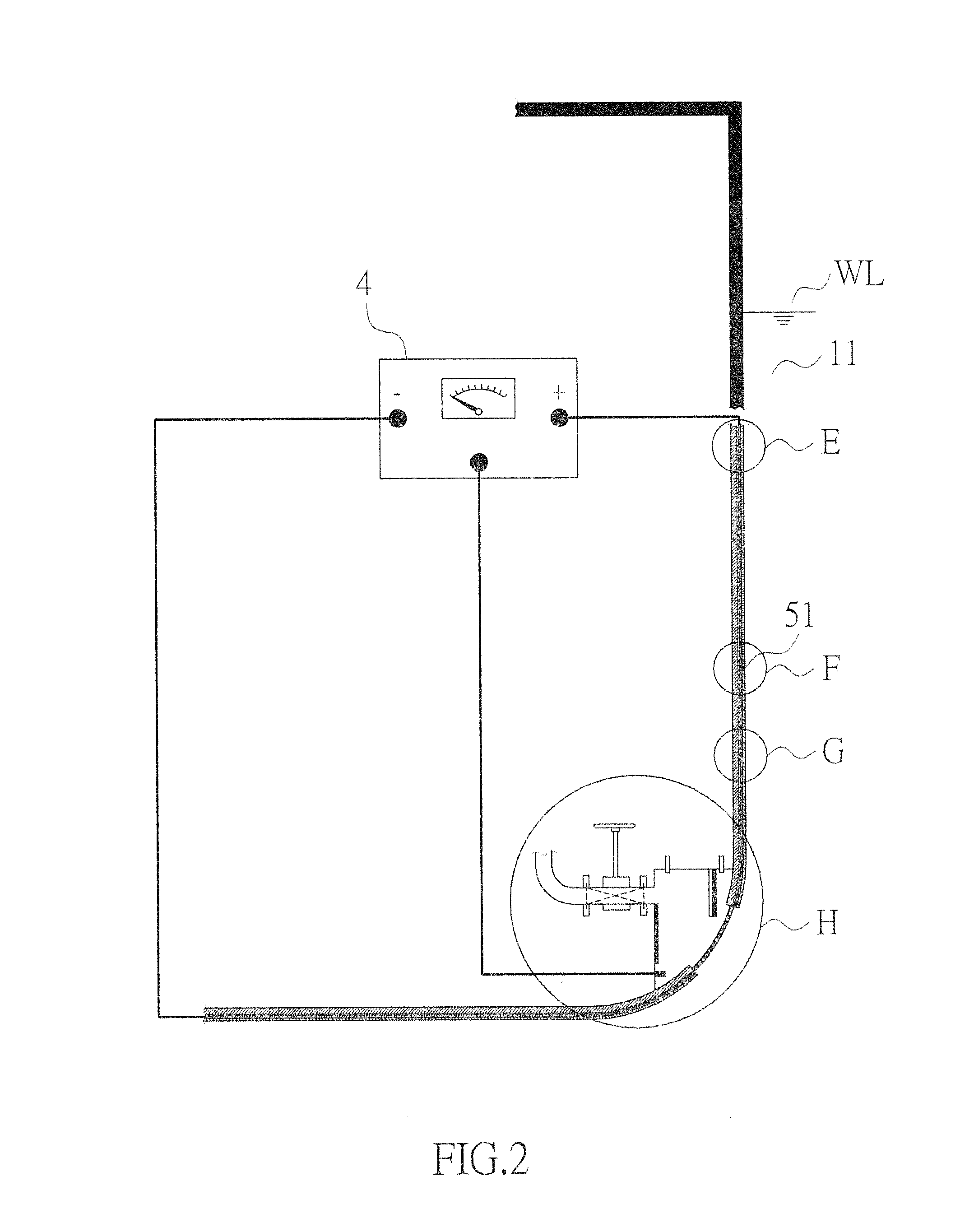
[0018]With reference to FIGS. 1 and 2, the invention provides an apparatus of friction reduction and biofouling prevention for the submerged portion of a carrier or maritime structure. The submerged portion can be the submerged hull 11 of a ship B, of an oil rig, of a wind power generator platform, or of a wharf. The term “submerged portion” means that portion of the carrier below the water line WL. In FIG. 1 the submerged portion of the carrier is the submerged hull 11 of a ship B, and the term “hull 11” will be used hereafter to indicate that portion of the hull 11 below the water line WL. FIG. 2 shows the general arrangement of the invention. The embodiment of the invention will be given in terms of water (preferably seawater) electro-catalysis.

[0019]With reference to FIGS. 2 and 3A, the apparatus of the invention shows the first anodic layer 2 coated on the outer surface of the hull 11. The first anodic layer 2 is made of metal-mixed oxide (MMO), which can be, but not limited to...


PUM

PropertyMeasurementUnit
thicknessaaaaaaaaaa
speedaaaaaaaaaa
current densityaaaaaaaaaa

Abstract

An apparatus for friction reduction and biofouling prevention is invented, which consists of an anodic electro-catalytic layer and a cathodic electro-catalytic layer installed on the submerged surface of a carrier. There is an insulating filling between the anodic layer and the cathodic layer. The layered coatings are applied with the use of electric arc spraying technique. A first DC power supply unit is connected to the anodic layer and the cathodic layer. The anodic layer, the cathodic layer, the DC power supply unit, and water together form the conducting path for water electro-catalysis. Hydrogen and oxygen gases are produced to form a thin gas film on the submerged surface to reduce friction and prevent biofouling on the carrier. Alternatively, the apparatus produces hydroxyl radicals to kill marine microorganisms and reduce the risk of biofouling and biocorrosion.

Description

BACKGROUND[0001]This invention concerns a layered coating and an apparatus with electro-catalytic ability for reducing ship's friction and preventing biofouling on submerged structures.[0002]Due to the gradual exhaustion of fossil fuels, the increasing fuel price is harsh to shipping companies worldwide. The increase of fuel consumption results from the frictional resistance and biofouling on the submerged hull of a moving ship.[0003]In the conventional approach of using micro-bubbles to reduce frictional resistance, compressed air is pushed by a blower to pass through porous plates located on the submerged hull. Micro-bubbles are then continuously generated on the outer surface of the submerged hull to reduce the frictional resistance on the sailing ship. The porous plates are usually located adjacent to the bow or where optimal reduction of frictional resistance can be obtained. The calculated friction reduction can be as high as 80%. But the friction reduction realized by this te...

Claims


Application Information

Patent Timeline
Patent Type & Authority Applications(United States)
IPC IPC(8): C09D5/16B63B1/38
CPCC09D5/1693B63B1/38B63B2001/387B63B59/04Y02T70/10Y10T428/263Y10T428/31678
Inventor WU, KEE-RONGSHYU, YU-TSUENHUNG, CHUNG-HSUANGWU, JIING-KAEYEH, CHIUNG-WEICHANG, SHUN-HSYUNG
Owner WU KEE RONG
Why Eureka
Try Eureka