
Transportation device

a technology for transporting devices and shock absorbers, applied in the directions of transportation and packaging, bumpers, vehicular safety arrangements, etc., can solve the problems of affecting the operation of trains, increasing costs, and affecting the effect of safety, so as to prevent frequent replacement of shock absorbers

Inactive Publication Date: 2008-10-02
HITACHI LTD
View PDF3 Cites 18 Cited by
  • Summary
  • Abstract
  • Description
  • Claims
  • Application Information

AI Technical Summary

Benefits of technology

[0008]The object of the present invention is to provide a transportation device with a shock absorbing device capable of turning the function of the shock absorber on and off according to the level of shock received during collision and to prevent frequent replacement of the shock absorber.
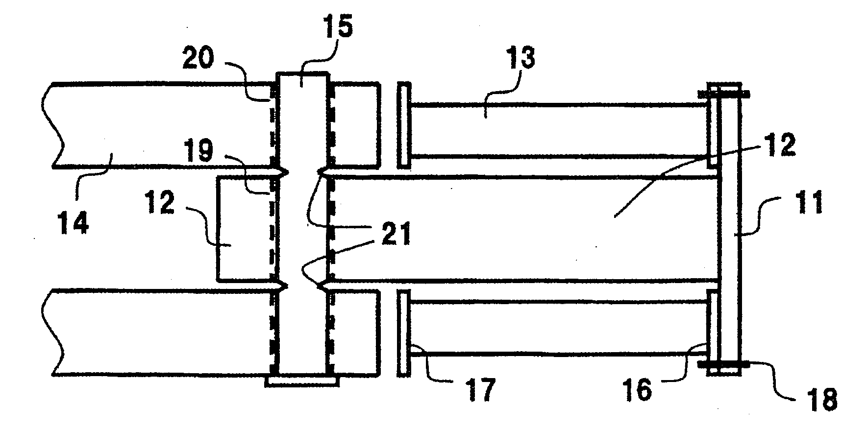
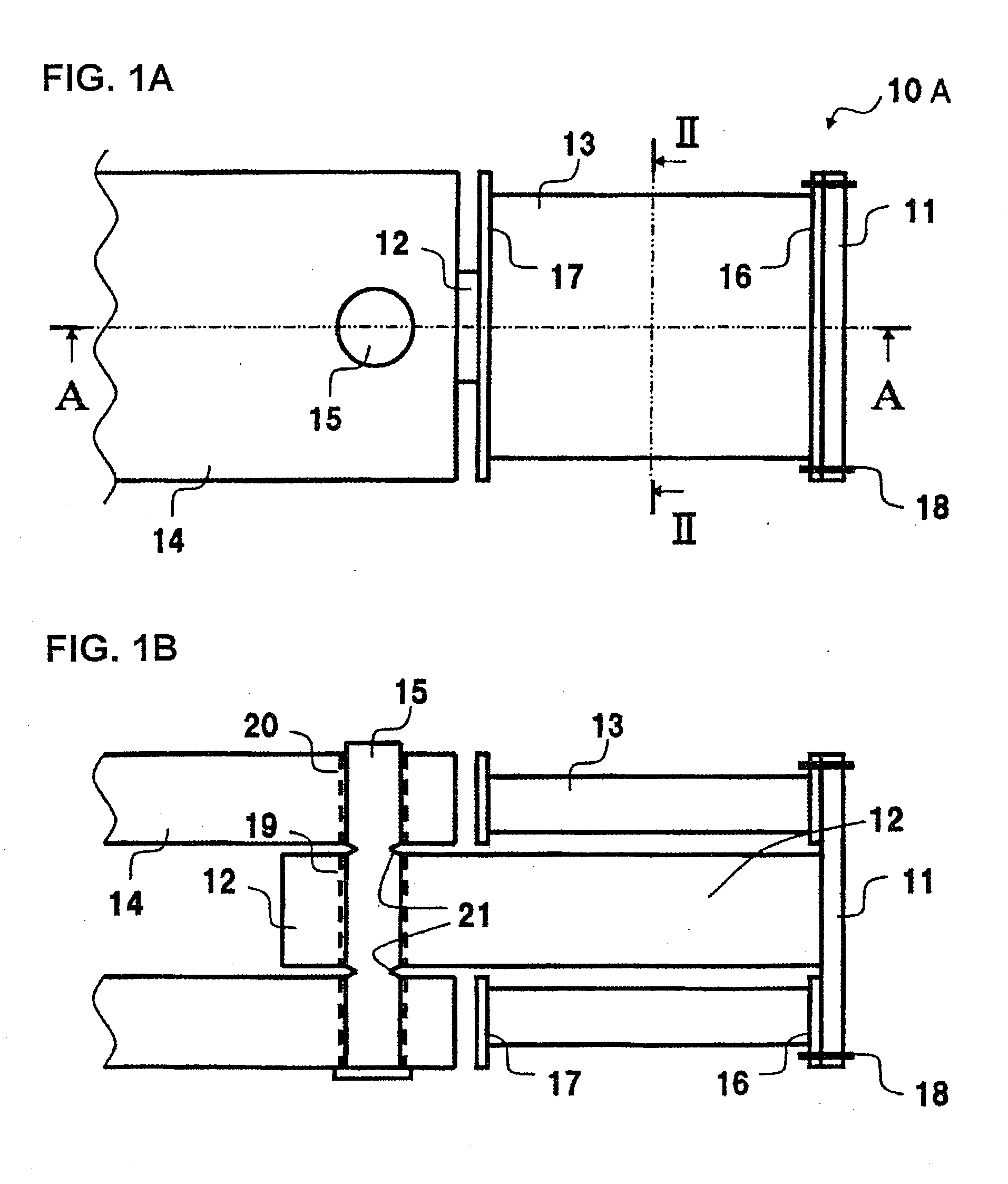
[0010]According to such arrangement, when the impact load is small, the load is not transmitted to the shock absorber, so that the load is not applied on the shock absorber and the shock absorber will not collapse. Therefore, compared to the prior art shock absorber that collapsed each time shock is applied, the costs and work related to replacing shock absorbers and to attach new absorbers can be cut down.

Problems solved by technology

Therefore, if the shock absorbers are designed to be easily collapsed by shock to absorb the shock effectively, the shock absorbers will receive load every time a minor collision occurs, according to which the shock absorbers must be replaced frequently, resulting in the hindrance of train operation and increase of costs.
However, if the shock absorbers are designed to have a strong structure in order to overcome such drawback, the shock absorbing property may be deteriorated and the shock absorbers may not function effectively when a large collision occurs.

Method used


Image

  • Transportation device
  • Transportation device
  • Transportation device

Examples


Embodiment Construction

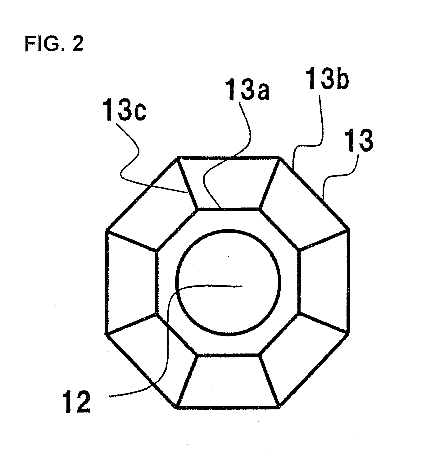
[0029]An embodiment of the present invention will be described with reference to FIGS. 1 through 3.

[0030]As illustrated in FIG. 3, a railway car body structure 5 is composed of a roof structure 1 constituting an upper plane thereof, two side structures 2 and 2 constituting the sides thereof, an underframe 3 constituting a lower plane thereof, and two end structures 4 and 4 constituting the ends thereof. The roof structure 1, the side structures 2 and 2, the underframe 3 and the end structures 4 and 4 are respectively formed by welding a plurality of extruded shape members. The extruded shape members constituting the roof structure 1, the side structures 2 and 2 and the underframe 3 are hollow shape members made of aluminum alloy, and the direction of extrusion thereof corresponds to the front-rear direction of the railway car body structure 5. The extruded shape members constituting the end structures 4 and 4 are shape members with ribs formed of aluminum alloy, and the direction of...


PUM


Abstract

The invention provides a shock absorbing structure capable of turning the function of the shock absorber on and off according to the level of shock during collision, thereby reducing the frequency of replacing shock absorbers. On a rear surface of a load operating unit 11 constituting a shock absorbing device 10A are attached a load transmitting shaft 12 and a shock absorber 13. The load transmitting shaft 12 is passed through the center of the shock absorber and is connected to a supporting unit 14 via a pin 15 that extends toward the radial direction. The rear end of the shock absorber 13 faces the supporting unit 14 with a clearance therebetween. The pin 15 has notched grooves 21 formed thereto. When small load is applied, the load is transmitted from the load operating unit 11 through the load transmitting shaft 12, the pin 15 and the supporting unit 14 to the main body, so that the load is not applied on the shock absorber 13. When large load is applied, the pin 15 breaks from where the notched grooves 21 are formed, by which the surface of the closing plate 17 collides against the supporting unit 14, so that the load is transmitted to the shock absorber 13 and the shock is absorbed effectively.

Description

[0001]The present application is based on and claims priority of Japanese patent application No. 2007-92504 filed on Mar. 30, 2007, the entire contents of which are hereby incorporated by reference.BACKGROUND OF THE INVENTION[0002]1. Field of the Invention[0003]The present invention relates to transportation devices including railway vehicles such as railway cars or monorail cars and automobiles anticipated to receive shock by collision. The present invention specifically relates to transportation devices equipped with a shock absorbing device composed of a shock absorber formed of a material having superior shock absorption property for absorbing the shock occurring during collision.[0004]2. Description of the Related Art[0005]In a conventional railway car, a crushable zone for absorbing the shock received during collision is desirably disposed in the car body so as to ensure the safety of passengers and crew during collision. With respect thereto, Japanese Patent No. 3725043 (pate...

Claims


Application Information

Patent Timeline
IPC IPC(8): B61F19/04B60R19/02
CPCB61D15/06B61G11/16B61F19/04
Inventor NAKAMURA, HIDEYUKIHAYASHI, SEIICHIKAWASAKI, TAKESHIMIYAMOTO, TOSHIHARU
Owner HITACHI LTD
Learn More