Plate bending equipment for metal pool production

A pool and plate technology, which is applied in the field of plate bending, can solve the problems of inconsistent bending angles of plates, uneven stress of plates, and low degree of automation, so as to avoid inconsistent bending angles, high degree of automation, and improve work efficiency Effect

Pending Publication Date: 2020-11-03
南京市园林规划设计院有限责任公司
View PDF0 Cites 5 Cited by
  • Summary
  • Abstract
  • Description
  • Claims
  • Application Information

AI Technical Summary

Problems solved by technology

[0003] Existing sheet metal bending equipment for metal pool production usually requires manual assisted bending, which has a low degree of automation, and it can only bend one side of the sheet at one time. When double-sided bending is required, the sheet needs to be reversed and bent again. The operation is troublesome, time-consuming and labor-intensive; when the existing metal pool production plate bending equipment bends the plate, the plate is prone to uneven force, resulting in inconsistent bending angles of the plate

Method used


Image

  • Plate bending equipment for metal pool production
  • Plate bending equipment for metal pool production
  • Plate bending equipment for metal pool production

Examples


Embodiment 1

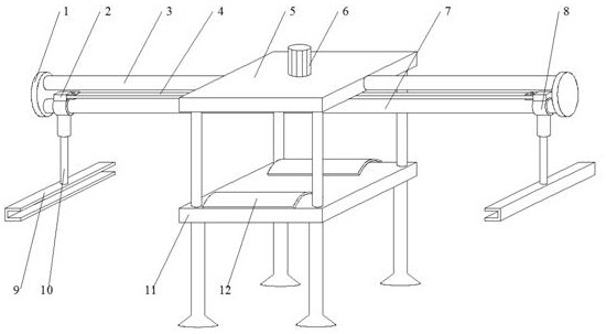
[0025] refer to Figure 1-2 , a metal pool production plate bending equipment, including a workbench 11, the four corners of the bottom of the workbench 11 are welded with support columns, both sides of the top of the workbench 11 are connected with splints 12 by elastic hinges, the top four corners of the workbench 11 Columns are all welded, and the same top plate 5 is welded on the top of the columns. The top plate 5 is provided with a reciprocating mechanism, the bottom of the reciprocating mechanism is provided with a bending mechanism, and a fixed structure is provided between the reciprocating mechanism and the top plate 5.

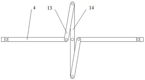
[0026] In the present invention, the reciprocating mechanism includes the first positive and negative motor 6, the rotating rod 14, the first connecting rod 13, the second connecting rod 4, the connecting block 2, the limit post 7 and the first collar 8, the first positive and negative motor 6 is installed on the top of the top plate 5, the output s...

Embodiment 2

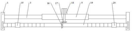
[0029] refer to image 3 The only difference between this embodiment and Embodiment 1 is that the reciprocating mechanism includes a second reversible motor 18, a screw mandrel 19, a second collar 15, a second bevel gear 16, a first bevel gear 17 and a third collar 20 , the second reversible motor 18 is installed on the top of the top plate 5, the output shaft of the second reversible motor 18 runs through the top plate 5 and is welded with the first bevel gear 17, the first bevel gear 17 is meshed with the second bevel gear 16, the second The center of the second bevel gear 16 runs through a threaded mandrel 19, and the two ends of the threaded mandrel 19 are respectively sleeved with a second collar 15 and a third collar 20. The end of the threaded mandrel 19 where the second collar 15 is located is provided with a positive thread, and the second collar 15 is provided with a positive thread. The inner wall of the second collar 15 is provided with a reverse thread, the end of...


PUM


Abstract

The invention discloses plate bending equipment for metal pool production. The equipment comprises a workbench, supporting columns are welded to the four corners of the bottom of the workbench correspondingly, clamping plates are connected to the two sides of the top of the workbench through elastic hinges correspondingly, stand columns are welded to the four corners of the top of the workbench correspondingly, and a top plate is welded to the tops of the stand columns. A reciprocating mechanism is arranged on the top plate, a bending mechanism is arranged at the bottom of the reciprocating mechanism, and a fixing structure is arranged between the reciprocating mechanism and the top plate. According to the plate bending equipment, the two ends of a plate can be bent at the same time, the automation degree is higher, and the working efficiency is improved; The problems of inconsistent bending angles and poor effect caused by non-uniform stress of the plate are avoided; and the plate isprevented from deviating in the bending process, and the steps of fixing and taking down the plate are simple, convenient and fast.

Description

technical field [0001] The invention relates to the technical field of plate bending, in particular to a plate bending equipment for producing metal pools. Background technique [0002] The metal pool uses metal to make the pool box, and different pool boxes are combined to create an irregular and rich pool effect. The main material of the metal pool is metal sheet, which needs to be bent into the required angle to facilitate installation. [0003] Existing sheet metal bending equipment for metal pool production usually requires manual assisted bending, which has a low degree of automation, and it can only bend one side of the sheet at one time. When double-sided bending is required, the sheet needs to be reversed and bent again. The operation is cumbersome, time-consuming and labor-intensive; when the existing metal pool production plate bending equipment bends the plate, the plate is prone to uneven force, resulting in inconsistent bending angles of the plate. [0004] A...

Claims


Application Information

Patent Timeline
Patent Type & Authority Applications(China)
IPC IPC(8): B21D5/01B21D43/00
CPCB21D5/002B21D5/01
Inventor 姜丛梅陈伟耿杉
Owner 南京市园林规划设计院有限责任公司
Why Eureka
Try Eureka