
Injection mold and injection molding process thereof

An injection mold and injection molding technology, applied in the field of injection molds, can solve the problems of increased cost, manual demoulding, poor molding quality of injection parts, etc., and achieve the effect of reducing production costs, improving production types, and ensuring uniform cooling.

Pending Publication Date: 2020-11-03
金华观瑞科技有限公司
View PDF8 Cites 7 Cited by
  • Summary
  • Abstract
  • Description
  • Claims
  • Application Information

AI Technical Summary

Problems solved by technology

[0003] However, there are still some defects in the design of the existing injection molds. First of all, the existing injection molds are all one machine and one set of models. Replace the corresponding model to achieve general processing, resulting in an increase in cost; secondly, the existing injection mold usually needs to be cooled and formed under natural conditions after injection molding, which not only prolongs the processing time of the injection molded parts but also naturally cools the injection molded parts The molding quality is poor. At the same time, the existing injection mold does not have a quick demoulding mechanism. After the injection molded parts are processed, manual demoulding is required. On the one hand, it is easy to cause damage to the injection molded parts, and on the other hand, the efficiency of injection molding processing is reduced

Method used


Image

  • Injection mold and injection molding process thereof
  • Injection mold and injection molding process thereof
  • Injection mold and injection molding process thereof

Examples


Embodiment Construction

[0038] The technical solutions of the present invention will be clearly and completely described below in conjunction with the embodiments. Apparently, the described embodiments are only some of the embodiments of the present invention, not all of them. Based on the embodiments of the present invention, all other embodiments obtained by persons of ordinary skill in the art without creative efforts fall within the protection scope of the present invention.

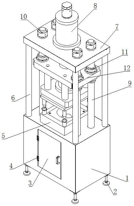
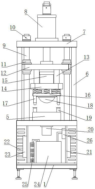
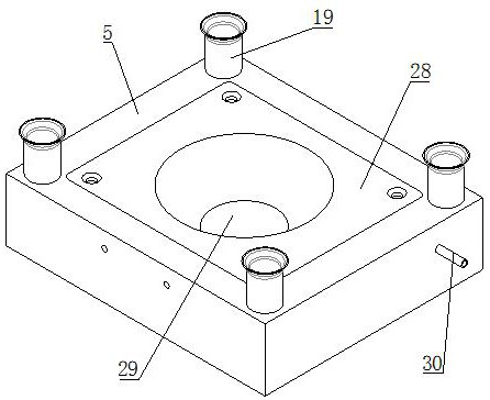
[0039] see Figure 1-11 As shown, an injection mold includes an injection molding bottom cabinet 1, a support foot 2, a cabinet door 3, a hinge 4, a lower mold base 5, a support column 6, a top plate 7, a first driving hydraulic cylinder 8, a lifting plate 12, and a connecting column 13. Upper mold base 14, upper mold mounting seat 16, injection molding upper mold 18 and injection molding lower mold 28; the four corners of the bottom of the injection molding base cabinet 1 are provided with supporting feet 2, and the suppor...


PUM


Abstract

The invention discloses an injection mold and an injection molding process thereof. A lower mold base is fixedly arranged in the center of the upper end of an injection molding bottom cabinet, a mounting groove matched with an injection molding lower mold is formed in the lower mold base, and the injection molding lower mold is detachably mounted on the lower mold base through bolts; and vertically upward supporting columns are fixedly connected to the four corners of the upper end of the injection molding bottom cabinet correspondingly, a top plate is fixedly connected to the upper ends of the supporting columns, and a vertically downward first driving hydraulic cylinder is fixedly installed at the center position of the upper end of the top plate. According to the injection mold, the upper surface and the lower surface of an injection molding part are cooled at the same time, uniform cooling of the upper surface and the lower surface of the injection molding part is guaranteed, the forming quality of the injection molding part is guaranteed while rapid cooling and shaping of the injection molding part are improved, the injection molding part obtained after injection molding is completed is ejected out of a female mold on the injection molding lower mold through a demolding ejection plate, rapid demolding of the injection molding part is achieved, and the injection molding part machining efficiency is improved.

Description

technical field [0001] The invention relates to the technical field of injection molds, in particular to an injection mold and an injection molding process thereof. Background technique [0002] Injection molding, also known as injection molding, is a molding method of injection and molding. The advantages of the injection molding method are fast production speed, high efficiency, automatic operation, various designs and colors, simple to complex shapes, large to small sizes, accurate product sizes, easy replacement of products, and complex shapes. Parts, injection molding is suitable for mass production and complex shape products and other molding processing fields. [0003] However, there are still some defects in the design of the existing injection molds. First of all, the existing injection molds are all one machine and one set of models. Replace the corresponding model to achieve general processing, resulting in an increase in cost; secondly, the existing injection m...

Claims


Application Information

Patent Timeline
IPC IPC(8): B29C45/03B29C45/26B29C45/73B29C45/17B29C45/40B29C33/30
CPCB29C45/03B29C45/26B29C45/73B29C45/7207B29C45/1742B29C45/4005
Inventor 不公告发明人
Owner 金华观瑞科技有限公司
Learn More