A glass fiber reinforced plastic winding pipe processing equipment

A technology for processing equipment and winding pipes, applied in the field of glass fiber reinforced plastic winding pipe processing equipment and processing equipment, can solve the problems of small application range of molds, low applicability, small adjustable range, etc., and achieves strong applicability and practicability. Internal structure The effect of tightness and improved processing quality

Active Publication Date: 2022-04-01
许绝电工股份有限公司
View PDF11 Cites 0 Cited by
  • Summary
  • Abstract
  • Description
  • Claims
  • Application Information

AI Technical Summary

Problems solved by technology

[0003] In order to overcome the deficiencies of the existing technology, a FRP winding pipe processing equipment with strong applicability and practicability, which can improve the processing quality of the winding pipe, can effectively solve the problem that the FRP winding pipe processing equipment in the prior art can be adjusted during use. Problems such as small scope, small application scope and low applicability of molds of the same equipment

Method used


Image

  • A glass fiber reinforced plastic winding pipe processing equipment
  • A glass fiber reinforced plastic winding pipe processing equipment
  • A glass fiber reinforced plastic winding pipe processing equipment

Examples


Embodiment 1

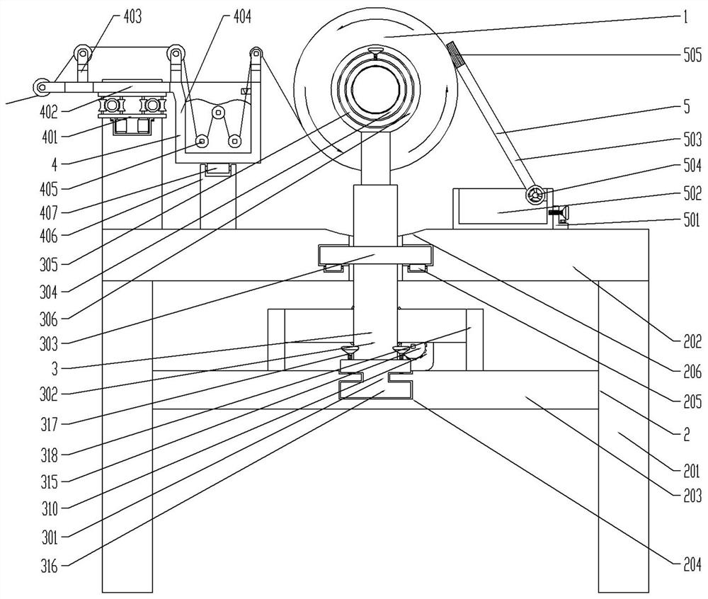
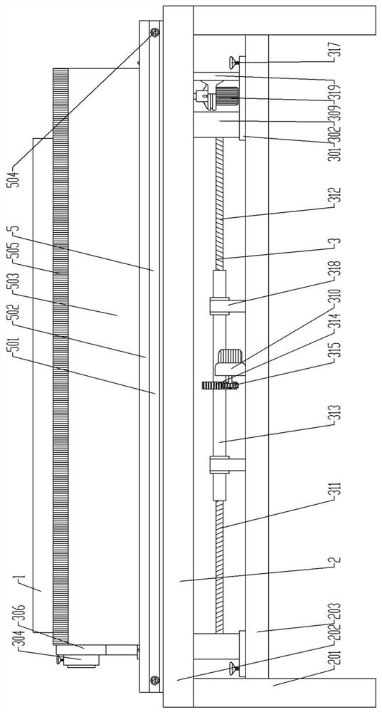
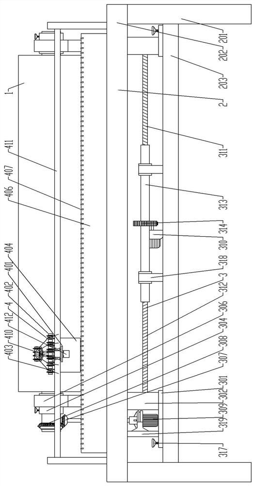
[0032] see figure 1 , figure 2 , image 3 , Figure 5 , a fiberglass winding pipe processing equipment, including a winding pipe mold 1, and also includes a support assembly 2, a retention assembly 3 and a wire feeding dipping assembly 4, and the retention assembly 3 is slidably arranged on the support assembly 2 In the middle, the wire feeding dipping assembly 4 is arranged on the supporting assembly 2, and the supporting assembly is used to support the retention assembly and the wire feeding dipping assembly. The supporting assembly 2 includes legs 201, upper support plate 202 and a lower support plate 203, the legs 201 are arranged at the corners of the upper support plate 202, the lower support plate 203 is fixedly arranged on the legs 201, the upper support plate 202 and the middle part of the lower support plate 203 Both are provided with chute 204, the chute of the upper support plate and the lower support plate are used for limiting the retention assembly, and the ...

Embodiment 2

[0044] The same as embodiment 1 will not be repeated, the difference is:

[0045] The upper support plate 202 is also provided with a scraping mechanism 5, the scraping mechanism 5 includes a retaining angle plate 501, a glue collecting groove 502 and a squeegee plate 503, and the retaining angle plate 501 is fixed to the upper supporting plate by bolts 202, easy to disassemble and install, the retaining angle plate 501 is connected to the glue collecting tank 502 through the retaining hand wheel 504, and connected through the retaining hand wheel, it is convenient to remove it to collect the glue recovered inside the glue collecting tank. The squeegee 503 is arranged inside the rubber collecting tank 502. The squeegee 503 and the rubber collecting tank 502 are hingedly connected. The hinged connection can adjust the angle of hanging overtime. It is suitable for winding pipes of various specifications. Connected by adjusting the hand wheel 317, the end of the scraper 503 is pr...


PUM


Abstract

The present invention relates to a glass fiber reinforced plastic winding pipe processing equipment, which includes a winding pipe mold, and also includes a supporting assembly, a retaining assembly and a wire feeding dipping assembly, the retaining assembly is slidably arranged in the middle of the supporting assembly, and the The wire feeding and dipping assembly is set on the support assembly. The FRP winding pipe processing equipment of the present invention can be adjusted in a wide range according to the length of the winding pipe mold when fixing the winding pipe mold through the retaining assembly. The adjustment of this equipment It has a wide range and can be applied to winding pipe molds of various lengths. It has strong applicability and practicability. This equipment also has a wire feeding and dipping mechanism. The wire can be fully dipped in glue when dipping, and the cable board can arrange the wires neatly when winding, making the internal structure of the finished product more compact, thereby improving the processing quality of the winding pipe.

Description

technical field [0001] The invention belongs to the field of winding pipe processing, and in particular relates to processing equipment, in particular to processing equipment for glass fiber reinforced plastic winding pipes. Background technique [0002] Wound pipe is a light, high-strength, pressure-resistant and corrosion-resistant non-metallic pipe. It is made of glass fiber with resin matrix weight and wound on the rotating mandrel layer by layer according to the process requirements. The pipe wall structure is reasonable and advanced. Give full play to the role of the material, increase the rigidity under the premise of satisfying the use strength, and ensure the stability and reliability of the product. When the existing winding pipe is processed, it needs to use the winding pipe processing equipment. The existing FRP winding pipe processing equipment can be adjusted in a small range when used, and the molds of the same equipment have a small application range and low ...

Claims


Application Information

Patent Timeline
Patent Type & Authority Patents(China)
IPC IPC(8): B29C70/32B29C70/38B29C70/54B29C33/30B29L23/00
CPCB29C70/32B29C70/382B29C70/54B29C33/30B29L2023/22
Inventor 袁小平李剑陶岩魏党召孙勇
Owner 许绝电工股份有限公司
Why Eureka
Try Eureka