
Guide bar cradle transmission device

A transmission device and bar technology, applied in the field of bar cradles, can solve the problems of complex transmission and small swing range of bar cradles

Pending Publication Date: 2020-11-03
FUJIAN XINYI MACHINERY TECH CO LTD
View PDF1 Cites 2 Cited by
  • Summary
  • Abstract
  • Description
  • Claims
  • Application Information

AI Technical Summary

Problems solved by technology

With this traditional structural design, the transmission of the bar cradle is relatively complicated, and the swing range is small

Method used


Image

  • Guide bar cradle transmission device
  • Guide bar cradle transmission device
  • Guide bar cradle transmission device

Examples


Embodiment Construction

[0062] In order to further explain the technical solution of the present invention, the following examples are described in detail.

[0063] refer to Figure 6-Figure 7 :

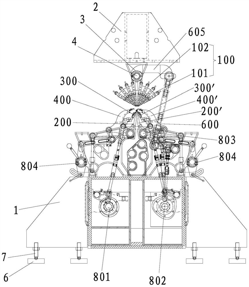
[0064] A kind of bar cradle transmission device, comprises for being installed on the beam 2 of warp knitting machine (will introduce in detail below), the sky shaft seat 3, the sky shaft 4, the bar device 100 and the bar shaker sleeved on the sky shaft 4 The frame transmission mechanism 600, the sky shaft 4 is rotatably installed on the sky shaft seat 3.

[0065]In this embodiment, the bar device 100 includes a bar cradle 101 and a bar cradle 102, and the bar cradle 101 includes a bar cradle arm 1011 for installing the bar 102 and is arranged in the middle of the bar cradle arm 1011. The connection end 1012, the connection end 1012 includes a first installation part 1013 and a second installation part 1014, a connection end through hole 1015 through which the sky shaft 4 can pass is formed between the fi...


PUM


Abstract

The invention relates to a guide bar cradle transmission device which comprises a line shaft seat, a line shaft, a guide bar device and a guide bar cradle transmission mechanism, the line shaft seat is used for being mounted on a beam of a warp knitting machine, the guide bar cradle transmission mechanism sleeves the line shaft, the line shaft is rotatably arranged on the line shaft seat in a penetrating manner, and the guide bar device comprises a guide bar cradle and guide bars mounted on the guide bar cradle. The guide bar cradle comprises a guide bar cradle arm for mounting the guide barsand a connecting end arranged in the middle of the guide bar cradle arm, the line shaft is fixedly connected with the connecting end, and the guide bar cradle transmission mechanism is fixedly connected with the line shaft. According to the guide bar cradle structure, the guide bar cradle and the guide bar cradle transmission mechanism are combined, the guide bar cradle and the guide bar cradle transmission mechanism are both fixed to the line shaft, and the line shaft is directly driven by the guide bar cradle transmission mechanism to control the guide bar cradle to swing left and right in areciprocating manner.

Description

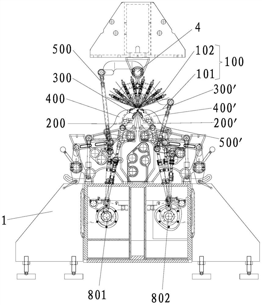
technical field [0001] The invention relates to the technical field of a bar cradle, in particular to a bar cradle transmission device. Background technique [0002] A traditional warp knitting machine, such as application number 201910016428.8, is disclosed in a Chinese invention patent application titled "A Double Needle Bed Warp Knitting Machine". figure 1 As shown, it includes a frame 1, a knitting device, a bar device 100 and a transmission device; the knitting device includes a symmetrical front / rear take-off part, a symmetrical front / rear needle bed part and a symmetrical front / rear sinking part , the transmission device includes a symmetrically arranged front / rear needle bed transmission mechanism, a symmetrically arranged front / rear sinking transmission mechanism, a bar cradle up swing transmission mechanism 500 and a bar cradle bottom swing transmission mechanism 500'; The transmission mechanisms each include a stripping bracket and a stripping plate, and the fron...

Claims


Application Information

Patent Timeline
Patent Type & Authority Applications(China)
IPC IPC(8): D04B27/24
CPCD04B27/24
Inventor 蔡美凉殷守国陈晓君
Owner FUJIAN XINYI MACHINERY TECH CO LTD
Learn More