
Self-adapted temperature sensor of gas range

A technology for temperature sensors and gas stoves, applied in thermometers, thermometer parts, thermometers with direct heat-sensitive electric/magnetic elements, etc., can solve the limitation of temperature measurement points, low temperature measurement accuracy, misoperation, etc. problems, to achieve the effects of strong fire and heat insulation capabilities, accurate temperature transmission, and high temperature measurement accuracy

Active Publication Date: 2011-08-31
HUNAN XUNDA JI TUAN YOU XIAN GONG SI
View PDF1 Cites 0 Cited by
  • Summary
  • Abstract
  • Description
  • Claims
  • Application Information

AI Technical Summary

Problems solved by technology

Using infrared temperature detection technology, because it is not a direct contact temperature measurement, the temperature measurement point is relatively limited, resulting in low temperature measurement accuracy, and is easily interfered by various environmental variables, causing misoperation
Using flame direct combustion thermocouple, because the collected temperature cannot reflect the internal temperature of the cooker, it can only be applied to the flameout protection device of the gas cooker
The telescopic temperature sensor published in Chinese Patent Application No. 200720062479.7 adopts thermocouple contact sensing technology. The thermocouple is close to the cooker. It has a compact structure and high temperature measurement accuracy. Ensure the accuracy of temperature measurement; the sensor head has a small range of motion, which may cause poor contact with cookware, and it is difficult to adapt to different cookware and different positions of cookware; the processing and assembly of parts are more complicated, so it is necessary to improve

Method used


Image

  • Self-adapted temperature sensor of gas range
  • Self-adapted temperature sensor of gas range

Examples


Embodiment Construction

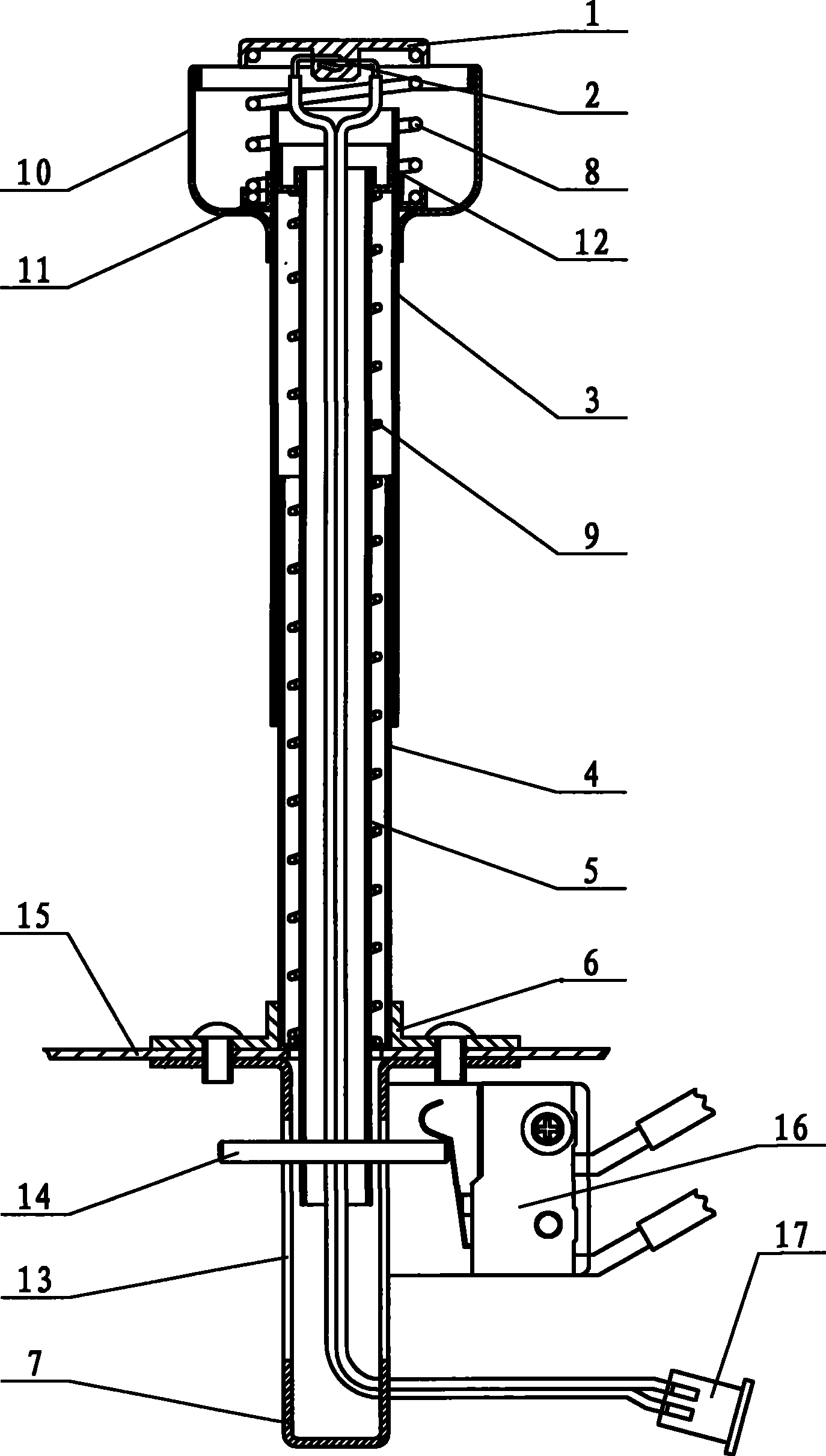
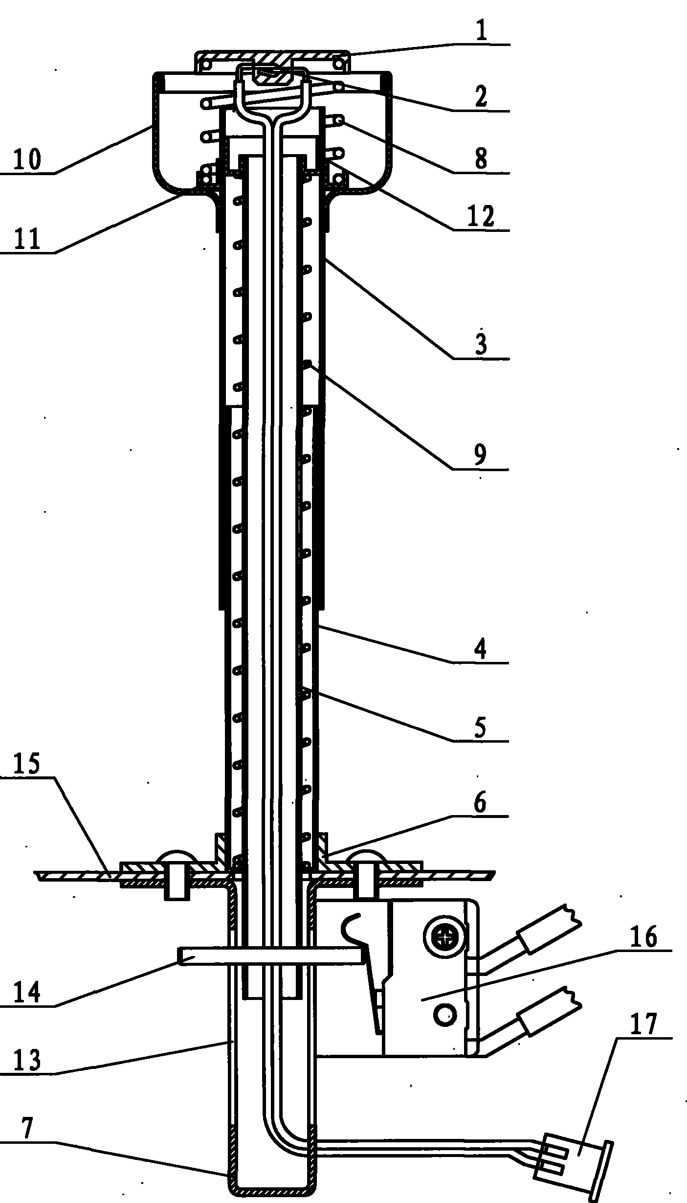
[0012] like figure 1 As shown, the adaptive temperature sensor of the gas cooker of the present invention includes a sensing cap 1, a thermocouple 2, a sliding sleeve 3, a guide sleeve 4, a guide rod 5, a positioning plate 6, a spring one 8, a spring two 9 and a guide frame 7 , the outer ring surface of the upper end of the sliding sleeve 3 is fixedly connected with a positioning ring 11 and a fireproof ring 10, the positioning ring 11 is installed in the fireproof ring 10, the inner ring surface of the upper end of the sliding sleeve 3 is fixedly connected with a positioning ring 2 12, and the guide rod 5 is A straight round pipe, the outer ring surface of its upper end is fixedly connected with the positioning ring 2 12, the lower end of the guide rod 5 is fixed with a shaft pin 14, the lower end of the guide sleeve 4 is fixedly connected with the positioning plate 6, and the spring 2 9 is installed in the guide sleeve 4 and set Hold the guide rod 5, its upper end is against...


PUM


Abstract

The invention relates to a self-adapted temperature sensor of a gas range, comprising a sensing cap, a thermoelectric couple, a sliding sleeve, a guide sleeve, a guide rod, springs and a guide frame. The external annuls surface of the upper end of the sliding sleeve is fixedly connected with a first positioning ring and a fireproof ring; the guide rod is a straight circular tube; the upper end ofthe first spring is abutted against and connected with the sensing cap and the lower end thereof is connected with the first positioning ring; the second spring is installed in the guide sleeve and sleeves the guide rod; the slide sleeve is sleeved on the guide sleeve; the head part of the thermoelectric couple is installed in the sensing cap; and conducting wires of the thermoelectric couple penetrate through the guide rod and the guide frame to be connected with a controller. The self-adapted temperature sensor of a gas range has compact structure, convenient installation, high temperature measurement accuracy and large swinging range of the sensing cap, can be adaptive to various cookers and the free placement of the cookers, and is especially suitable for embedded type intelligent control gas ranges and fume-free control gas ranges.

Description

technical field [0001] The invention relates to a temperature sensor, in particular to an adaptive temperature sensor applied to intelligent control of civil gas stoves. Background technique [0002] The temperature sensors currently used in civil gas cookers include infrared temperature detectors and thermocouple contact temperature sensors. Using infrared temperature detection technology, because it is not directly contacting the temperature measurement, the temperature measurement point is relatively limited, resulting in low temperature measurement accuracy, and it is easily interfered by various environmental variables, causing misoperation. The use of flame direct combustion thermocouples can generally only be applied to the flameout protection device of gas cookers because the collected temperature cannot reflect the internal temperature of the cooker. The telescopic temperature sensor published in Chinese Patent Application No. 200720062479.7 adopts thermocouple con...

Claims


Application Information

Patent Timeline
Patent Type & Authority Patents(China)
IPC IPC(8): G01K7/02G01K1/08
Inventor 伍斌强胡正军伍奕
Owner HUNAN XUNDA JI TUAN YOU XIAN GONG SI
Learn More