Simulation system and method of laser projection module

A technology of laser projection and simulation system, which is applied in the field of 3D imaging, can solve the problems of costing a lot of time and energy, and the design efficiency of laser projection modules is not high, and achieve the effects of cost saving, design optimization and easy design

Active Publication Date: 2020-11-03
DONGGUAN VISIONX-TECH CO LTD
View PDF6 Cites 1 Cited by
  • Summary
  • Abstract
  • Description
  • Claims
  • Application Information

AI Technical Summary

Problems solved by technology

However, due to the many application scenarios of laser projection modules, it usually takes a lot of time and effort to design a laser projection module that meets the requirements of the application scenarios, resulting in low efficiency in the design of laser projection modules

Method used


Image

  • Simulation system and method of laser projection module
  • Simulation system and method of laser projection module
  • Simulation system and method of laser projection module

Examples


Embodiment Construction

[0044] The technical solutions in the embodiments of the present application will be described below with reference to the drawings in the embodiments of the present application.

[0045] In order to facilitate the understanding of the solution, the laser projection module is introduced here first.

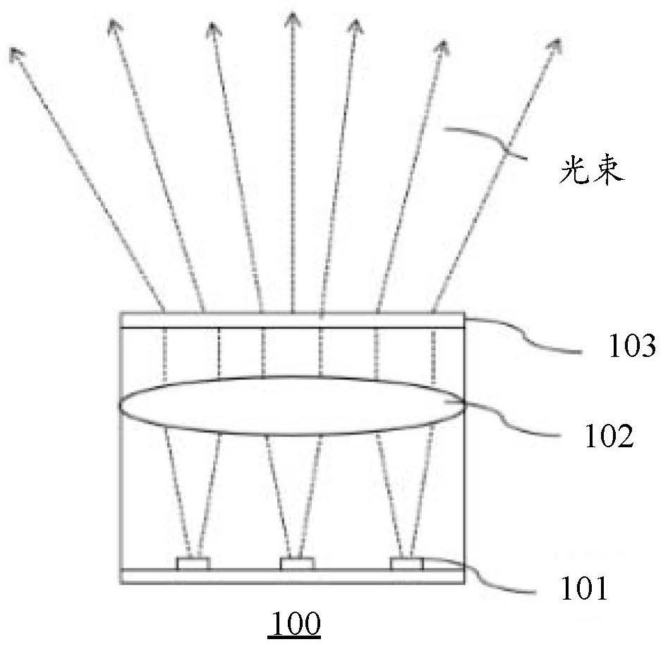
[0046] see figure 1 , figure 1 It is a schematic diagram of a laser projection module 100 provided in the embodiment of the present application.

[0047] In this embodiment, the laser projection module 100 may include: a light source 101 , a collimating mirror 102 and a diffractive optical element 103 .

[0048] Exemplarily, the light source 101 may be a VCSEL light source, and the VCSEL light source includes a plurality of sub-light sources, and the plurality of sub-light sources may be arranged in a two-dimensional pattern on the semiconductor carrier. Compared with traditional light sources, it has the advantages of small size, small divergence angle and energy concentration...


PUM


Abstract

The invention provides a simulation system and method for a laser projection module, and the system comprises a light source unit, a collimating lens unit, a DOE unit, a projection screen unit, a first optical model between the light source unit and the collimating lens unit, a second optical model between the collimating lens unit and the DOE unit, and a third optical model between the DOE unit and the projection screen unit. The light source unit is used for simulating emitted beams; The first optical model is used for determining the incident angle of the light beam collimated by the collimating mirror unit to the DOE unit; the collimating mirror unit is used for collimating the light beams emitted by the light source unit; the second optical model is used for determining the type of diffraction generated when the collimated light beam enters the DOE unit; the DOE unit is used for projecting a speckle pattern based on the collimated light beams; the third optical model is used for determining coordinates of the speckle pattern on the plane where the projection screen unit is located according to the incident angle and the diffraction type; and the projection screen unit is usedfor displaying the speckle pattern on the plane based on the coordinates.

Description

technical field [0001] The present application relates to the technical field of 3D imaging, in particular, to a simulation system and method of a laser projection module. Background technique [0002] 3D (3-Dimension, three-dimensional) imaging is more and more widely used in the field of consumer electronics, for example, in the fields of 3D scanning, face payment, and scene modeling. 3D imaging technology can not only image the target object, but also obtain the depth information of the target object. Structured light or TOF (Time Of Flight) depth cameras are currently the most widely used 3D imaging devices. [0003] The core component of the depth camera: the laser projection module, which can be used to project speckle patterns into space to measure the depth of structured light. The laser projection module mainly includes a VCSEL (Vertical-Cavity Surface-Emitting Laser) light source, a collimator and a diffractive optical element (Diffractive Optical Element, referr...

Claims


Application Information

Patent Timeline
IPC IPC(8): G02B27/42G02B27/48
CPCG02B27/4266G02B27/48
Inventor 陈展耀戴书麟刘风雷
Owner DONGGUAN VISIONX-TECH CO LTD
Why Eureka
Try Eureka