Supercharge Your Innovation With Domain-Expert AI Agents!

Laser color mixing structure

A laser and color mixing technology, applied in optics, optical components, instruments, etc., can solve problems such as complex structure and narrow color gamut of color mixing

Pending Publication Date: 2020-11-03
广州市焦汇光电科技有限公司
View PDF0 Cites 0 Cited by
  • Summary
  • Abstract
  • Description
  • Claims
  • Application Information

AI Technical Summary

Problems solved by technology

The working principle of color mixing of traditional DLP projectors is to project each single basic monochromatic light separately, and then superimpose and mix colors on the screen by each basic monochromatic light. It can be seen that the DMD module is an indispensable core of traditional DLP projectors. Components, the DMD module has the disadvantage of complex structure, so the traditional DLP projector has the disadvantage of complex structure, in addition, the traditional DLP projector also has the disadvantage of too narrow color gamut for color mixing

Method used


Image

  • Laser color mixing structure
  • Laser color mixing structure
  • Laser color mixing structure

Examples


Embodiment 1

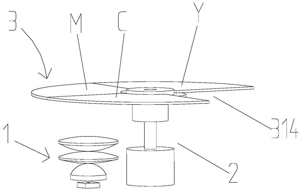
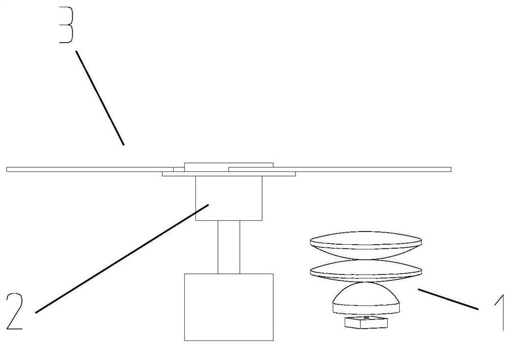
[0028] Figure 1 to Figure 3 The structure of the laser color mixing structure according to an embodiment of the present invention is schematically shown.

[0029] like Figure 1 to Figure 3 As shown in the figure, the laser color mixing structure includes a control system, a laser light source 1, a motor 2 and a color wheel piece 3; wherein, the laser light source 1 and the motor 2 are electrically connected to the control system respectively, and the motor 2 is set to drive the color wheel piece 3. Rotation; the color wheel 3 is provided with a plurality of color areas, and the plurality of color areas are arranged in a circular array around the rotation center axis of the color wheel 3; the plurality of color areas contain at least all basic colors of any color mixing mode; laser The light emitting direction of the light source 1 is aligned with the color area. In this embodiment, the laser light source 1 emits white laser light, and the rotating shaft of the motor 2 is c...

Embodiment 2

[0039] The difference between this embodiment and the first embodiment:

[0040] Figure 4 The structure of the laser color mixing structure of another embodiment of the present invention is schematically shown.

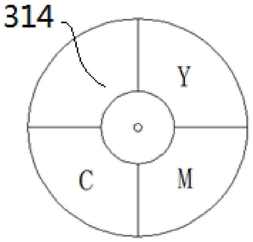
[0041] like Figure 4 As shown, in this embodiment, n color mixing function chip groups are arranged on the color wheel 3; the plurality of color areas also include n blank areas 314, and the blank areas 314 are separated between two adjacent color mixing function chips between groups; where n is a natural number greater than 0. and n≥2. Specifically, in this embodiment, n=2. In this way, by arranging a plurality of color mixing function film groups on the color wheel piece 3, within one rotation period of the color wheel piece 3, a higher cyclic switching frequency is obtained between the basic colors of the mixed color light, which is not easy to distinguish , so as to obtain better color mixing effect. At the same time, the laser light source 1 can also prov...


PUM


Abstract

The invention discloses a laser color mixing structure, and the structure comprises a control system, a laser light source, a motor and a color wheel piece, wherein the laser light source and the motor are in electric control connection with the control system, and a motor is arranged to drive the color wheel piece to rotate; the color wheel piece is provided with a plurality of color areas, and the color areas are arranged around the rotation center axis of the color wheel piece in a circular array mode; the plurality of color regions at least comprise all basic colors of any color mixing mode; the light-emitting direction of the laser light source is aligned with the color area. Mixed color light is projected. Meanwhile, the percentage of each basic color in the mixed color light can besmoothly adjusted by controlling the irradiation time of the laser light source and the rotating speed of the motor, so that an electrodeless color mixing function is achieved, and the mixed color light with a wider color gamut can be projected.

Description

technical field [0001] The invention relates to a laser color mixing structure. Background technique [0002] The color mixing working principle of traditional DLP projectors is to use a combination of color separation filters such as red, green, blue, and white, which can separate the transmitted white light, and separate different monochromatic lights through the color wheel sequence. A full-color image is projected through the DMD and its projection lens. When the red light hits the DMD, the lens is tilted and flipped according to the position and intensity of the red information, and the green and blue light and video signals also work according to this principle. The image formed on the surface of the DMD can be projected through the projection lens. The working principle of color mixing of traditional DLP projectors is to project each single basic monochromatic light separately, and then each basic monochromatic light is superimposed and mixed on the screen. It can b...

Claims


Application Information

Patent Timeline
Patent Type & Authority Applications(China)
IPC IPC(8): G03B21/20G02B26/00
CPCG02B26/008G03B21/2033G03B21/206
Inventor 不公告发明人
Owner 广州市焦汇光电科技有限公司
Features
  • R&D
  • Intellectual Property
  • Life Sciences
  • Materials
  • Tech Scout
  • Unparalleled Data Quality
  • Higher Quality Content
  • 60% Fewer Hallucinations
Learn More