
A broadband h-plane t-shaped waveguide

A broadband and waveguide technology, applied in the field of broadband H-plane T-shaped waveguide, can solve the problem of narrow bandwidth and achieve the effects of simple structure, small phase influence, and easy process design and processing

Active Publication Date: 2022-05-06
NO 54 INST OF CHINA ELECTRONICS SCI & TECH GRP
View PDF7 Cites 0 Cited by
  • Summary
  • Abstract
  • Description
  • Claims
  • Application Information

AI Technical Summary

Problems solved by technology

[0004] The purpose of the present invention is to solve the problem that the relatively narrow bandwidth of single-frequency use is relatively narrow in the existing H-plane T-shaped waveguide rectangular waveguide interface, and provide a broadband H-plane T-shaped waveguide, which can meet the needs of equal or unequal divisions. It has many advantages such as wide bandwidth, excellent index, compact structure and easy processing.

Method used


Image

  • A broadband h-plane t-shaped waveguide
  • A broadband h-plane t-shaped waveguide
  • A broadband h-plane t-shaped waveguide

Examples


Embodiment Construction

[0029] The technical solution of the present invention will be further described in detail below in conjunction with the accompanying drawings.

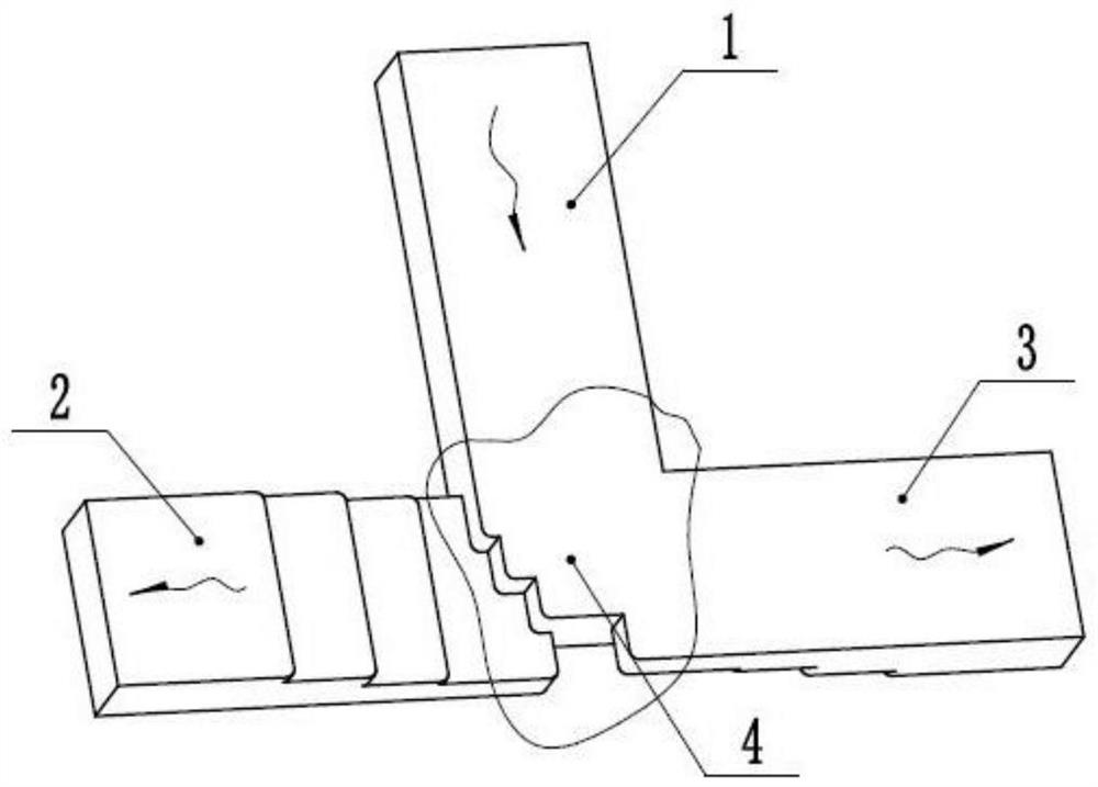
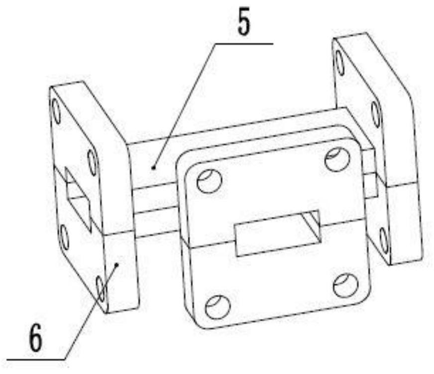
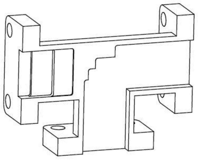
[0030] Such as Figure 1~3 As shown, a broadband H-plane T-shaped waveguide, the T-shaped waveguide cavity includes a common waveguide 1, a first branch waveguide 2, a second branch waveguide 3 and a central waveguide stack 4, and the shape is distributed in a T-shaped structure; The T-shaped waveguide electrically belongs to the H-plane T-shaped waveguide, and the first branch waveguide 2 and the second branch waveguide 3 are located on the broadside plane of the common waveguide 1; the T-shaped waveguide can be split into upper T The T-shaped waveguide block 5 and the lower T-shaped waveguide block 6 are finally formed by welding or screwing.

[0031] Further, the central waveguide stack 4 is formed by direct lamination of upper and lower layers of reverse curved waveguides, and there is no metal or other dielectric spacer layer b...


PUM


Abstract

The invention discloses a broadband H-plane T-shaped waveguide, which belongs to the field of waveguide technology. The common waveguide is a hollow rectangular straight waveguide section, the first branch waveguide and the second branch waveguide are located on the broadside plane of the common waveguide, the first and second branch waveguides are rectangular waveguide sections with step impedance transformation, and the steps of the two rise The direction is opposite, and the central waveguide stack is directly laminated by the upper and lower layers of bent waveguides with opposite bending directions. The invention has the characteristics of wide bandwidth of standing wave ratio, wide bandwidth of power division ratio and wide bandwidth of phase consistency, simple structure and easy processing. The invention solves the problem of power distribution and synthesis in the antenna broadband feeding network system, and can meet the requirements of most station-type antennas for equally divided or unequally divided waveguides.

Description

technical field [0001] The invention relates to the field of waveguide technology, in particular to a broadband H-plane T-shaped waveguide. Background technique [0002] In the field of microwave antenna communication, the power division network and the power combination network are common passive subsystems in various station antenna feeder networks. Specifically, the power division network forms include microstrip line structure, coaxial structure, and media integration. Various types of waveguide and metal waveguide structures. The metal waveguide cavity power division network is widely used in microwave communication systems due to its low insertion loss and high power capacity, and the T-shaped waveguide is the core unit of the waveguide cavity power division network and power combination network in the feed network. Use more in . Although the T-shaped waveguide structure is small, it directly determines the bandwidth of the antenna. With the continuous improvement of...

Claims


Application Information

Patent Timeline
Patent Type & Authority Patents(China)
IPC IPC(8): H01P3/123
CPCH01P3/123
Inventor 孙立杰秦光远袁朝晖张博孙焕金李振生阮云国
Owner NO 54 INST OF CHINA ELECTRONICS SCI & TECH GRP
Learn More