
Oil-water separation system and kitchen waste treatment equipment with the same

A technology of oil-water separation and separation barrel, which is applied in the direction of separation method, liquid separation, immiscible liquid separation, etc., which can solve the problems of incomplete separation, need for manual cleaning, and inconvenient use, so as to improve the effect of oil-water separation and promote oil-water separation , the effect of moisture content reduction

Active Publication Date: 2021-09-24
HEFEI AIRWREN AUTOMATIC EQUIP CO LTD
View PDF1 Cites 0 Cited by
  • Summary
  • Abstract
  • Description
  • Claims
  • Application Information

AI Technical Summary

Problems solved by technology

[0003] However, there are still obvious defects in its use: 1. The above-mentioned device has only one separation chamber, and the oil-water mixture can only achieve one-stage separation, which may lead to incomplete separation; 2. The above-mentioned device passes through the air Floating pumps are used to increase the amount of air bubbles in the mixture, thereby improving the separation efficiency of oil particles and liquids in wastewater, but the cost of air flotation pumps is usually high, which is not convenient for mass promotion and use, and the air flotation pump is set in the center of the bottom. The coverage of the bubbles is very limited, and it can only supplement the mixture in the middle position to promote oil-water separation, but its effect on the surrounding mixture is negligible, resulting in the improvement of the oil-water separation effect is not obvious, and the input and output are not directly proportional; 3. Since the oil-water mixture still contains a small amount of solid debris, the air flotation pump in the above device is easily polluted by the precipitated debris after a period of use, and manual cleaning is required, which is time-consuming and laborious, and inconvenient to use

Method used


Image

  • Oil-water separation system and kitchen waste treatment equipment with the same
  • Oil-water separation system and kitchen waste treatment equipment with the same

Examples


Embodiment Construction

[0023] The following will clearly and completely describe the technical solutions in the embodiments of the present invention with reference to the accompanying drawings in the embodiments of the present invention. Obviously, the described embodiments are only some, not all, embodiments of the present invention. Based on the embodiments of the present invention, all other embodiments obtained by persons of ordinary skill in the art without making creative efforts belong to the protection scope of the present invention.

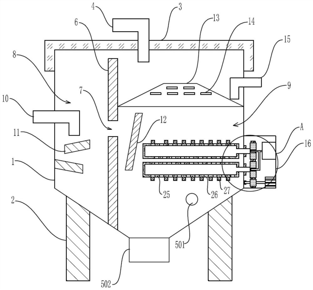
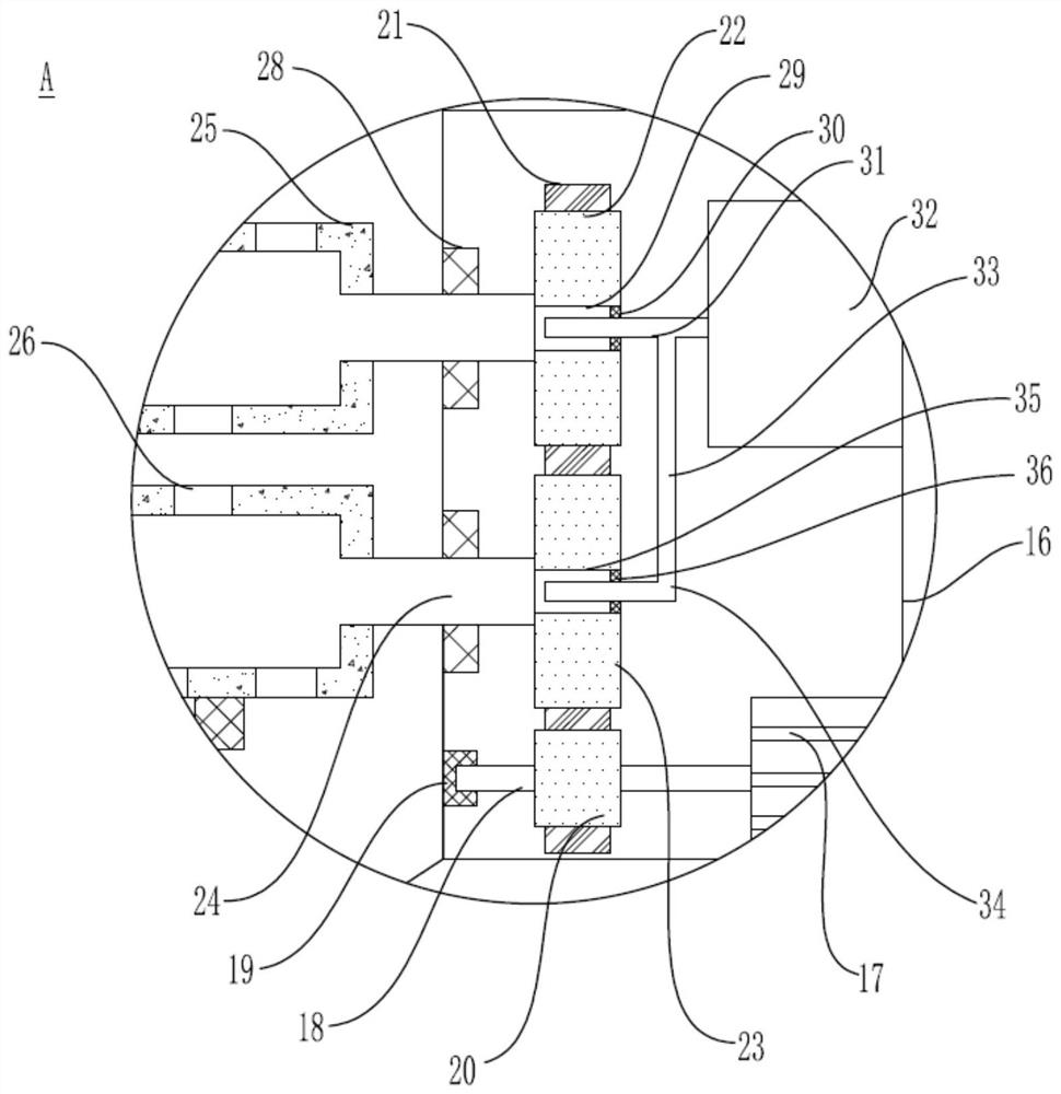
[0024] see Figure 1-2 , the present invention provides a technical solution:

[0025] An oil-water separation system, comprising a separation barrel 1, the bottom of the separation barrel 1 is fixedly provided with a support frame 2, the separation barrel 1 is a structure with an open top, and a top cover 3 is detachably arranged on the top of the separation barrel 1, and the top cover 3 penetrates A ventilation pipe 4 is provided, and the bottom of the sepa...


PUM


Abstract

The invention discloses an oil-water separation system and a kitchen waste treatment device equipped with the system, including a separation barrel; an oil collecting plate is fixedly arranged on the upper part of the secondary separation chamber, and an oil overflow groove is arranged on the oil collecting plate hole, an oil discharge pipe is arranged above the oil spill hole; a plurality of foam increasing holes are opened on the foam increasing pipe, and a plurality of cleaning brushes are fixedly arranged on the foam increasing pipe, and the first small ring A first air intake pipe is movably arranged in the bearing, and the second air inlet pipe is movably arranged in the second small ring bearing. The invention provides an oil-water separation system. The setting of the buffer plate can prevent the pre-separated oil and water from mixing again. The foam increasing tube can increase the amount of air bubbles in the mixture to promote oil-water separation. The coverage is wider and the foam increasing holes are not easy to be blocked. And it can be cleaned automatically during use. The present invention also provides a kitchen waste treatment device with the system, which is easy to use and is very worthy of popularization.

Description

technical field [0001] The invention relates to the technical field of kitchen waste treatment, in particular to an oil-water separation system and kitchen waste treatment equipment equipped with the system. Background technique [0002] In the prior art, a disc-type oil-water separator with the application number "201510063891.X" includes a support frame and a separation barrel. The body of the separation barrel is cylindrical, the bottom of the barrel is conical, and the bottom of the separation barrel is There is a slag discharge port and a top cover on the top. There is a conical oil collecting plate inside the separation barrel. There are several oil overflow slots on the cone, an oil discharge pipe is provided on one side of the separation barrel, a water inlet pipe is provided on one side of the separation barrel, and a drain pipe is provided on the other side, and the center of the outlet end of the drain pipe The line is 3 cm to 5 cm lower than the center line of t...

Claims


Application Information

Patent Timeline
Patent Type & Authority Patents(China)
IPC IPC(8): B01D17/02B09B3/00
CPCB01D17/02B01D17/0205B09B3/80
Inventor 龙梅郭润峰高小朋
Owner HEFEI AIRWREN AUTOMATIC EQUIP CO LTD
Learn More