Clamp for hardware machining

A fixture and hardware technology, applied in the field of fixtures for hardware processing, can solve the problems of complex fixture structure, high manufacturing cost, and inconvenient production, and achieve the effects of wide applicability, control of manufacturing cost, and easy operation

Pending Publication Date: 2020-11-06
安徽红专包装制品科技有限公司
View PDF8 Cites 0 Cited by
  • Summary
  • Abstract
  • Description
  • Claims
  • Application Information

AI Technical Summary

Problems solved by technology

[0003] The purpose of the present invention is to solve the problem of high manufacturing cost caused by the complex structure of the existing existing fixture, and the fixture can only hold the same workpiece, which has low applicability and brings great inconvenience to production. , and propose a fixture for metal processing

Method used


Image

  • Clamp for hardware machining
  • Clamp for hardware machining
  • Clamp for hardware machining

Examples


Embodiment Construction

[0032] The technical solutions of the present invention will be clearly and completely described below in conjunction with the embodiments. Apparently, the described embodiments are only some of the embodiments of the present invention, not all of them. Based on the embodiments of the present invention, all other embodiments obtained by persons of ordinary skill in the art without creative efforts fall within the protection scope of the present invention.

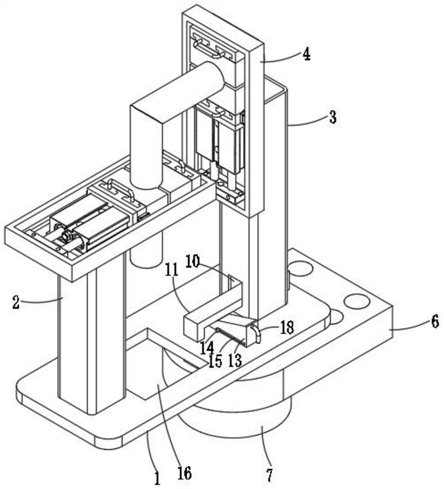
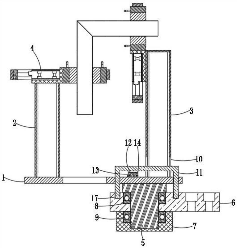
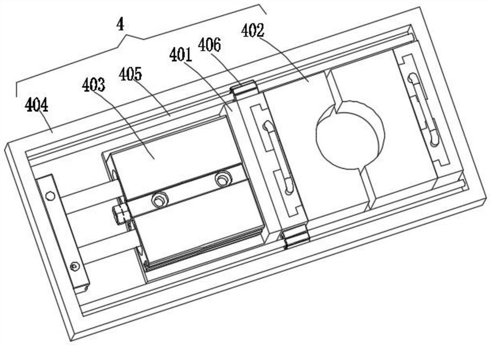
[0033] see Figure 1-12 As shown, a fixture for metal processing includes a base plate 1, and a second square hole 16 is provided on the left side of the base plate 1. When the workpiece is long, it is convenient for the workpiece to pass through the base plate 1. The left and right sides of the upper end surface of the base plate 1 are fixedly connected respectively. There are a first pillar 2 and a second pillar 3, the height of the second pillar 3 is greater than the height of the first pillar 2, a clamping mechanism 4 i...


PUM


Abstract

The invention discloses a clamp for hardware machining. The clamp for hardware machining comprises a bottom plate. The left side and the right side of the upper end face of the bottom plate are fixedly connected with a first strut and a second strut correspondingly, clamping mechanisms are mounted on the first strut and the second strut, a rotary seat is fixedly connected to the bottom end face ofthe right side of the bottom plate, a base is mounted on the rotary seat, the bottom end of the rotary seat is in threaded connection with a cover sleeve, and counter bores with the same size are formed in the cover sleeve and the base. The functionality of the device is guaranteed under the condition that the simple structure is kept, the manufacturing cost is effectively controlled, the clamp is convenient to produce and manufacture and is used and popularized in small enterprises, especially, as for connector welding of round pipes, the form and location tolerance after workpieces are formed is greatly increased, the machining precision is effectively improved, the applicability is high, the replacement manner is simple and convenient, and the operation is easy; and as the device is provided with a rotating mechanism, a worker can more rapidly adjust the working faces of the workpieces conveniently, and the working efficiency is effectively improved.

Description

technical field [0001] The invention relates to a jig for metal processing, in particular to a jig for metal processing, belonging to the technical field of hardware processing. Background technique [0002] Hardware processing can also be called metal processing. Turning, milling, planing, grinding and boring refer to various metal devices made of iron, steel, aluminum and other metals through forging, rolling, cutting, and other physical processing. Fixtures are indispensable in workpiece processing. When used, the fixture can not only hold the workpiece to facilitate the worker's operation, but also make the workpiece not easy to move, which can effectively improve the precision and speed up the work efficiency during processing. , it is difficult to guarantee the shape and position tolerance of the workpiece after forming. The existing fixture structure is complex, which leads to high manufacturing cost, which is not easy to promote in small enterprises, and the fixture ...

Claims


Application Information

Patent Timeline
Patent Type & Authority Applications(China)
IPC IPC(8): B23Q3/08
CPCB23Q3/08
Inventor 葛德雷
Owner 安徽红专包装制品科技有限公司
Why Eureka
Try Eureka