Molded sight tube for fluid level verification apparatus

a technology of fluid level verification and sight tube, which is applied in the direction of lighting and heating apparatus, instruments, machines/engines, etc., can solve the problems of long and expensive annealing process, draw lines in the elongated tube, and inability to accurately study the annealing process, etc., to improve geometrical tolerance, reduce stress, and save cost

Inactive Publication Date: 2018-10-25
OIL RITE CORP
View PDF3 Cites 0 Cited by
  • Summary
  • Abstract
  • Description
  • Claims
  • Application Information

AI Technical Summary

Benefits of technology

[0023]An intended benefit of the invention in manufacturing of the at least one annular groove for the o-rings or seals having reduced stress as compared to grooves produced with prior art manufacturing processes, and the improved geometrical tolerances for the at least one annular groove provide for an exact fit for each seal or o-ring or seal.
[0024]An intended benefit of the invention is the manufacturing of sight tubes having vastly improved clarity.
[0025]An intended benefit of the invention is a significant cost savings due to reduced manufacturing costs and reduced material costs.
[0026]An intended benefit of the invention is the manufacturing of sight tubes with reduced long-term drainage between the fluid level verification apparatus and the sight tube.
[0027]An intended benefit of the invention is the manufacturing of a molded sight tube which reduces the environmental effects of humidity upon the sight tube.

Problems solved by technology

However, the extrusion process produces draw lines in the elongated tube due to wear in the extrusion die as a result of use.
However, the annealing process is lengthy and expensive.
Further, the annealing process is not an exact science.
Further, nylon sight tubes possess a yellow tint which is undesirable in many applications.
Additionally, prior art applications of Trogamid® have a yellow color when processed and are subject to hazing.
Machining of grooves in the sight tube near its opposed ends produces high stress within the sight tube, especially at the sharp corners formed by the groove cutting process.
This process lends itself to “crazing” (microscopic cracks), extra machining, and the potential for design failure.
However, the prior art confronts a perennial issue, eventual leakage between a fluid level verification apparatus and a sight tube due to environmental conditions.
Vibrations and temperature changes eventually cause the sealing action between the fluid level verification apparatus and the sight tube to be compromised.

Method used


Image

  • Molded sight tube for fluid level verification apparatus
  • Molded sight tube for fluid level verification apparatus
  • Molded sight tube for fluid level verification apparatus

Examples


Embodiment Construction

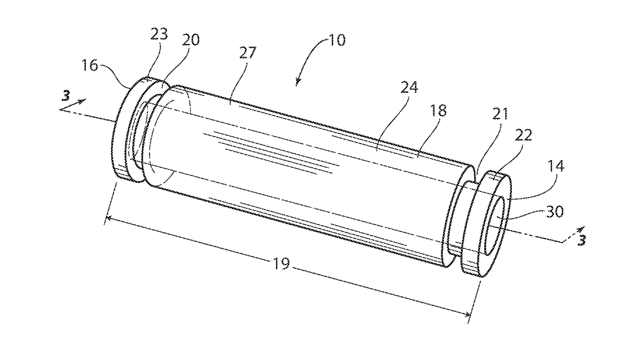
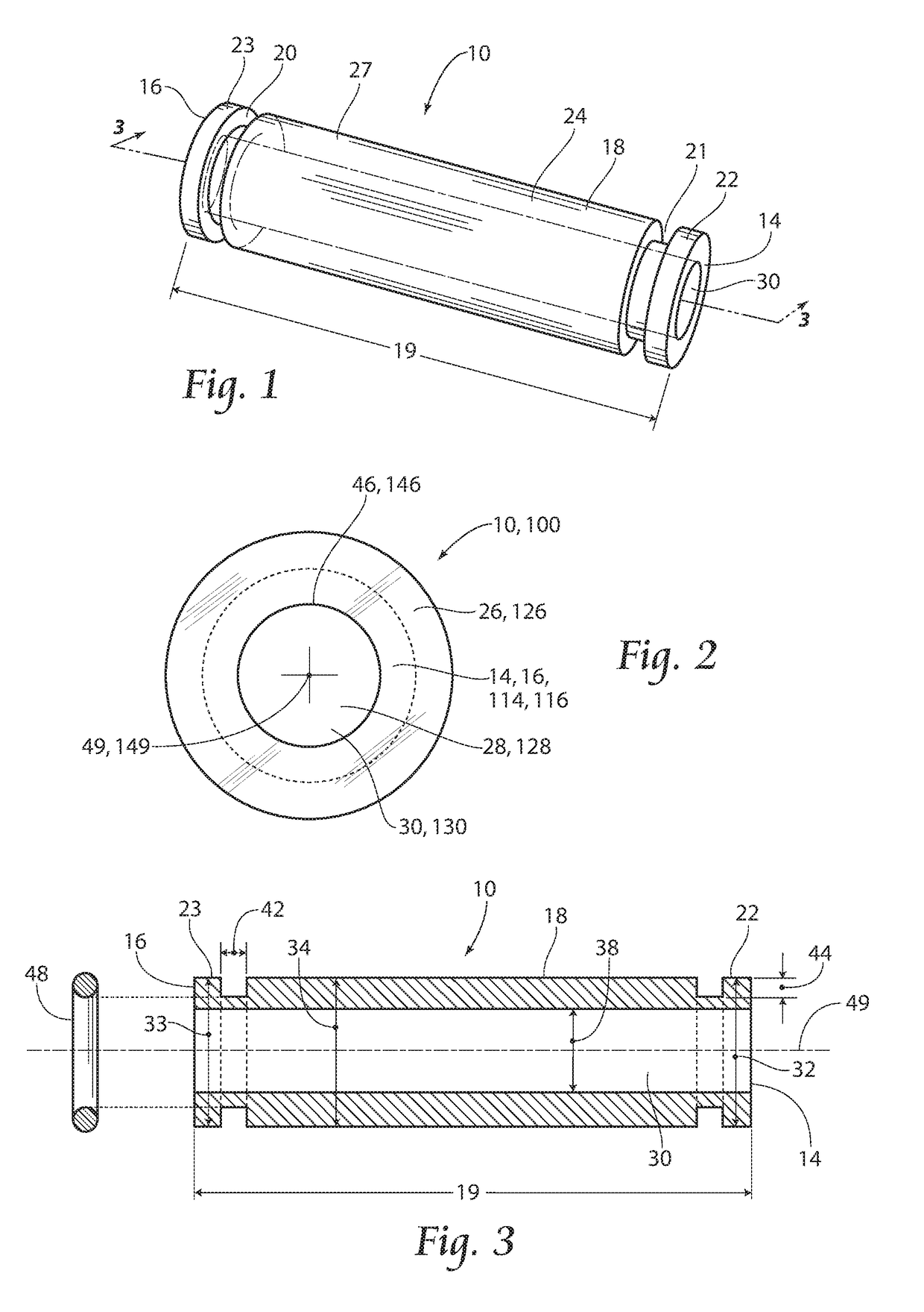
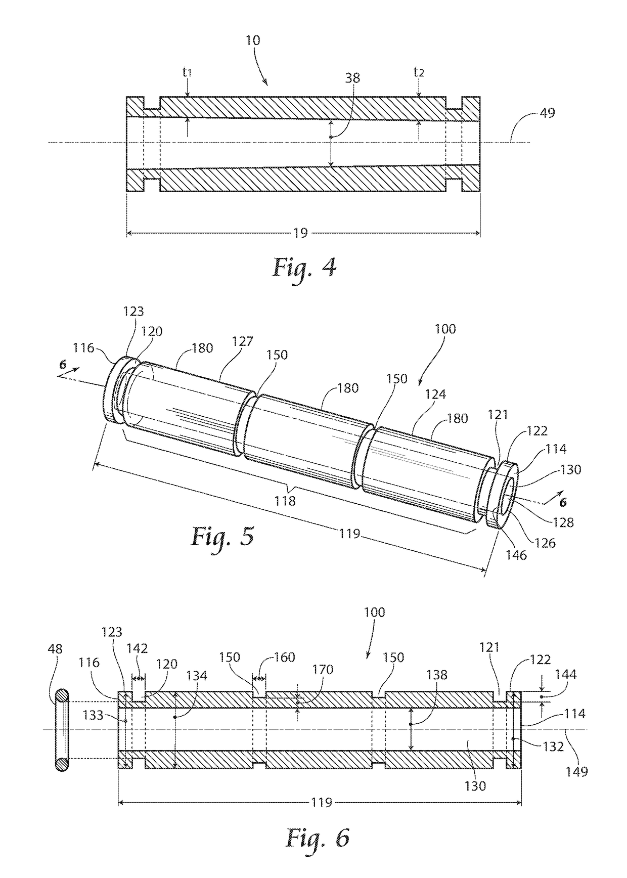
[0034]With attention to FIG. 1, a sight tube manufactured by a first embodiment of the present invention, and FIG. 5, a sight tube manufactured by a second embodiment of the present invention, a process for molding the sight, tube (10, 100) is described. The first embodiment involves molding the sight tube 10. The second embodiment involves molding the sight tube 100. Molding of the sight tube (10, 100) results in an intended benefit of the invention being a significant reduction in stresses within the sight tube by eliminating the machining process for creation of an at least one annular groove (20, 21, 120, 121). Additionally, molding of the sight tube (10, 100) results in an intended benefit of the invention which is the sight tube is ready for use after the molding process requiring no machining of the sight tube dimensions. Further, molding of the sight, tube (10, 100) results in an intended benefit, of the invention which is a significant cost savings due to reduced manufactur...


PUM


Abstract

A method for molding an improved sight tube for fluid level related applications comprising molding annular grooves a predetermined distance from respective sight tube ends, a conduit substantially traveling about central axis, along the length of the sight tube, with substantially constant or varying diameter, and a second embodiment of the invention comprising molding secondary annular grooves in addition to the above described features, to reduce the potential for leakage between a fluid level verification apparatus end pieces and the sight tube and to reduce material and manufacturing costs for manufacturing the sight tubes.

Description

RELATED APPLICATION[0001]This application is a continuation-in-part of co-pending U.S. patent application. Ser. No. 14 / 754,191, filed 29 Jun. 2015.BACKGROUND OF THE INVENTION[0002]The present invention relates generally to a fluid level verification apparatus which is operable to measure the amount of fluid present in an object of interest, such as a tank, machine, or other article of manufacture, and more specifically, to a sight tube utilized in the fluid level verification apparatus which may be manufactured using a molding process.[0003]Sight tubes are a component of a fluid level verification apparatus and known in the art for indicating fluid levels in the vessel to which the apparatus is attached. Prior art fluid verification devices have typically included a transparent tube or inspection window, which is connected in particular relation to the holding tank, and which provides a quick and convenient means by which an observer may visually verify the level of the fluid presen...

Claims


Application Information

Patent Timeline
Patent Type & Authority Applications(United States)
IPC IPC(8): G01F23/02F22B37/78
CPCG01F23/02F22B37/78
Inventor BOLDT, CAROLYN M.WECH, MICHAEL J.
Owner OIL RITE CORP
Why Eureka
Try Eureka