Pre-screwing device

A pre-screwing and mounting frame technology, applied in the direction of wrenches, screwdrivers, manufacturing tools, etc., can solve the problems of low assembly efficiency and high labor cost, and achieve the effect of compact structure, strong versatility and reasonable design

Pending Publication Date: 2020-11-06
SICHUAN GUORUAN SCI & TECH DEV CO LTD
View PDF0 Cites 3 Cited by
  • Summary
  • Abstract
  • Description
  • Claims
  • Application Information

AI Technical Summary

Problems solved by technology

[0003] Manual assembly has problems such as low assembly efficiency and high labor costs. With the development of technology, the automatic assembly system of wheel set front covers based on machine vision has become possible. In the automatic assembly system of wheel set front covers, usually At the position corresponding to each bolt, there are rotating shafts for matching with the bolts and driving the bolts to rotate (one end of the rotating shaft is provided with a torsion part matching with the heads of the bolts), and the rotating shafts are usually installed on the installation through bearing seats. frame, in order to drive the bolts to rotate under the drive of the motor, so as to achieve the purpose of automatically pre-tightening the bolts; different (that is, the diameters of the base circles are different), correspondingly, the base circles where the through holes (bolts) on the front cover are located will also change accordingly. Pre-twist device for front cover assembly

Method used


Image

  • Pre-screwing device
  • Pre-screwing device
  • Pre-screwing device

Examples


Embodiment 1

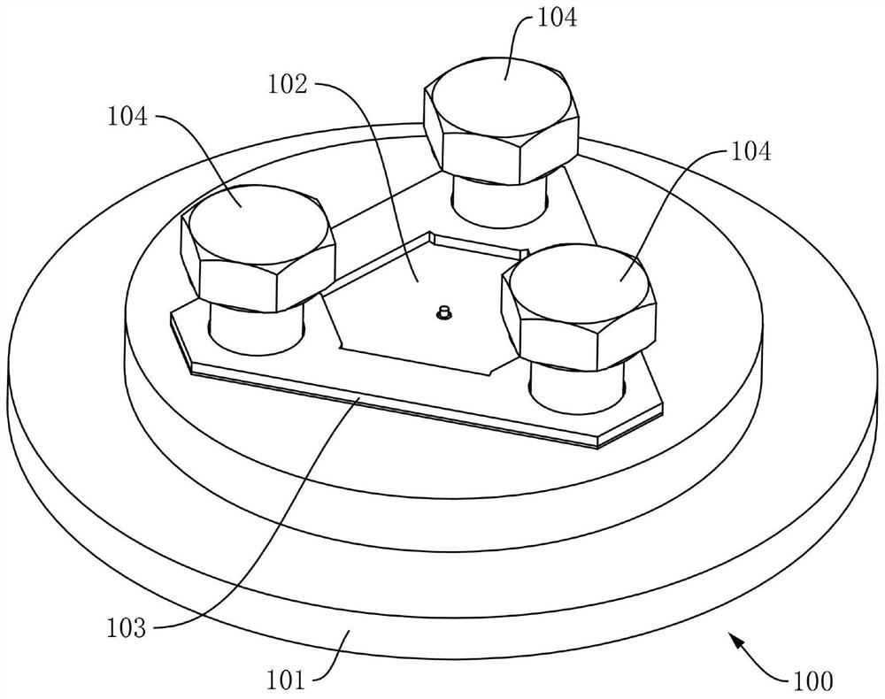
[0052] Such as Figure 2-Figure 16 As shown, this embodiment provides a pre-tightening device, including a mounting frame 300, a driving motor 501, and at least three rotating shafts 506, one end of which is provided with a torsion portion 508 adapted to the head of the bolt 104, The rotating shafts 506 are movably mounted on the mounting frame 300 through the bearing seats 400 respectively, and the rotating shafts 506 are respectively arranged uniformly along the circumferential direction of the same circle, and the positions of the bearing seats 400 can be adjusted along the radial direction of the circle respectively, so that Adapt to different types of front cover assemblies 100,

[0053] The drive motor 501 is used to drive the rotating shafts 506 to rotate so as to tighten the bolts.

[0054] In this embodiment, at least three rotating shafts are provided to match the number of bolts in the front cover assembly 100, and each rotating shaft 506 is evenly arranged along t...

Embodiment 2

[0077] In order to solve the force balance problem of each rotating shaft 506, the main difference between this embodiment 2 and the above-mentioned embodiment 1 is that in the pre-tightening device provided by this embodiment, the mounting frame 300 includes a first support body 308 and a second support body 308 support body 309, such as Figure 11 and Figure 12 As shown, the first support body 308 and the second support body 309 are connected through several support members 304, and there is a gap between the first support body 308 and the second support body 309, so as to install transmission components,

[0078] The first support body 308 and the second support body 309 are respectively provided with strip-shaped slots 302 with the same number and the same position, and the rotating shaft 506 is respectively connected to the first support body 308 and the second support body 309 through two bearing seats 400, Such as Figure 11 and Figure 12 As shown, and the first su...

Embodiment 3

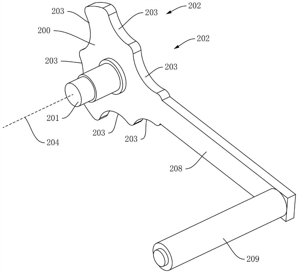
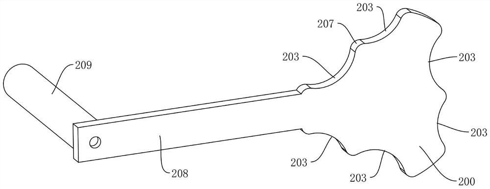
[0084] In order to solve the locking problem of the rotating shaft 506 or the bearing seat 400, the main difference between this embodiment 3 and the above-mentioned embodiment 2 or embodiment 1 is that the pre-tightening device provided by this embodiment also includes a number of springs 306. One end of the spring 306 is respectively connected with the bearing seat 400, and the other end is respectively connected with the support body 301. The spring 306 is used to provide the bearing seat 400 with an elastic force in the radial direction and directed to the central axis of the second mounting part 303, such as Figure 13 As shown, the setting of the spring 306 can provide the bearing seat 400 with an elastic force in the radial direction and directed to the central axis of the second mounting part 303, so that each bearing seat 400 or the rotating shaft 506 arranged on the bearing seat 400 can press the adjustment member 200 The limit groove 203, that is, the bearing seat 40...


PUM


Abstract

The invention relates to a pre-screwing device. The pre-screwing device comprises a mounting frame, a driving motor and at least three rotating shafts, wherein a torsion part matched with the head ofa bolt is arranged at one end of each rotating shaft; the rotating shafts are movably mounted on the mounting frame through bearing blocks correspondingly; the rotating shafts are uniformly arranged in the circumferential direction of the same circle; the positions of the bearing blocks can be adjusted in the radial direction of the circle; and the driving motor is used for driving the rotating shafts to rotate. The pre-screwing device is compact in structure and reasonable in design, the positions of the rotating shafts can be adjusted conveniently and efficiently so as to be suitable for front cover assemblies of different models, the universality is higher, synchronous adjustment and synchronous locking functions of the rotating shafts can be realized, and the rotating shafts can be positioned in the same circumferential direction before and after adjustment and in the adjustment process.

Description

technical field [0001] The invention relates to the technical field of rail transit equipment, in particular to a pre-twisting device. Background technique [0002] In the technical field of rail transportation equipment, the wheel set is an important part of the locomotive in contact with the rail. In the prior art, the wheel set usually needs to be installed in cooperation with the axle box device (abbreviated as the axle box), because the axle box The part that connects the wheel set and the bogie or the body of the two-axle car on the neck, mainly used to transfer the weight and load of the car body to the wheel set, lubricate the journal, and reduce running resistance; the existing axle box device usually includes a front cover assembly , the front cover assembly includes a front cover (or called an end cover, a pressure plate), a nameplate, a stop piece and a number of bolts, the front cover, the nameplate and the stop piece are respectively provided with through holes...

Claims


Application Information

Patent Timeline
Patent Type & Authority Applications(China)
IPC IPC(8): B25B13/48B25B23/16B25B23/00
CPCB25B13/48B25B23/00B25B23/16
Inventor 翟大庆屈良基
Owner SICHUAN GUORUAN SCI & TECH DEV CO LTD
Why Eureka
Try Eureka