Lifting equipment of fire pump

A water pump and fire-fighting technology, which is applied in the direction of mechanical equipment, pumps, pump devices, etc., can solve the problems of water pump boosting effect, water flow direction change, etc., to achieve the effects of weakening the pumping effect, smooth water flow, and reducing mutual collisions

Inactive Publication Date: 2020-11-06
成都常瑞满郎商贸有限公司
View PDF0 Cites 0 Cited by
  • Summary
  • Abstract
  • Description
  • Claims
  • Application Information

AI Technical Summary

Problems solved by technology

[0003] Based on the discovery of the inventors above, the existing methods mainly have the following disadvantages, such as: when the water flow passes through the water pump for pressurization, since the space in the water pump uses multiple conical grooves as the booster port, and the conical The connecting end surface of the tank and the water pump is usually provided with a raised block as a fixation. When the water flows through the pump, it is easy to hit the raised block to form a backflow, so that the flow direction of the water flow is changed, and it impacts the water flow itself, so that the boosting effect of the pump is reduced. influences

Method used


Image

  • Lifting equipment of fire pump
  • Lifting equipment of fire pump
  • Lifting equipment of fire pump

Examples


Embodiment 1

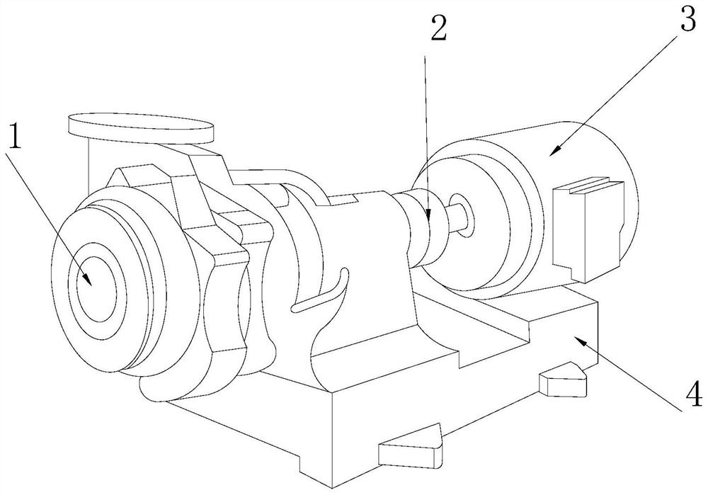
[0027] as attached figure 1 to attach Image 6 Shown:

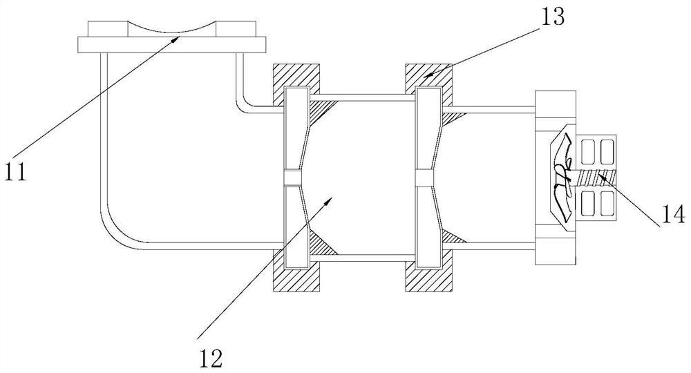
[0028] The invention provides a fire pump lifting device, the structure of which includes a pressurizing device 1, a power shaft 2, a motor 3, and a support seat 4. The pressurizing device 1 is installed on the left end surface of the power shaft 2 by welding, and the power The right end surface of the shaft 2 is inlaid with the motor 3, and the motor 3 is embedded and installed directly above the support base 4, and the support base 4 is located below the right side of the pressurizing device 1; the pressurizing device 1 includes an inlaid tube 11 , a pressurizing tube 12, an embedding ring 13, and a power paddle 14, the inlaying tube 11 is inlaid and mounted on the left side of the upper end of the pressurizing device 1, and the pressurizing tube 12 is nested and connected to the left side of the power paddle 14 , the embedding ring 13 is installed on the longitudinal outer end surface of the pressurizing pipe 12 by w...

Embodiment 2

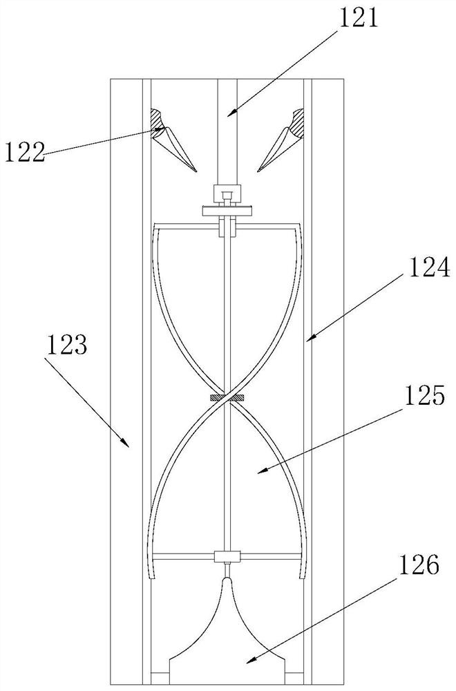
[0036] as attached Figure 7 to attach Figure 8 As shown: the circulation block 126 includes a cone 261, an inlay column 262, a fixed ring 263, a water seepage piece 264, and a connecting plate 265. The outer end surface of the column 262 is inlaid with a fixed ring 263, and the fixed ring 263 is installed on the inner end surface of the pipe wall 123 by welding. The water seepage sheet 264 wraps around the lateral outer end surface of the cone 261. The fixing ring 263 is at the center, and the cone 261 has a conical arc outer contour, which can effectively slow down the impact force of the water flow when the water flow hits from above and below.

[0037] Wherein, the water seepage sheet 264 includes an airtight patch 641, an inlay block 642, a fitting opening 643, and a diagonal flow block 644. connected, the mosaic block 642 is embedded and installed on the inner end surface of the water seepage sheet 264, the fitting opening 643 is set on the upper right side of the dia...


PUM


Abstract

The invention discloses lifting equipment of a fire pump. The lifting equipment structurally comprises pressurized equipment, a power shaft, a motor and a supporting seat. The pressurized equipment ismounted on the end face of the left side of the power shaft in a welded manner, the end face of the right side of the power shaft is connected with the motor in an inlaid manner, the motor is mountedover the supporting seat in a build-in manner, the supporting seat is located below the right side of the pressurized equipment, when spiral strips rotate, moving blocks mounted on the inner end faces of the spiral strips in a build-in manner can drive currents to converge and flow to an intermediate point, and the rotating speed of a movable blade is increased; and by means of the lifting equipment, the effect of the stable liquidity of the currents is achieved through the cooperation of the liquidity of the currents and a balance mechanism while flow of the currents can be effectively guaranteed, and the situation that power is dissipated due to mutual collisions in flow of the currents, and the water pumping effect of the pump is weakened can be effectively avoided.

Description

technical field [0001] The invention belongs to the field of fire protection, and more specifically relates to a fire pump lifting device. Background technique [0002] The fire pump lifting equipment is a way to pressurize the space inside the pump, so that the water flowing through the pump can flow to higher floors, avoiding the problem that it is difficult to supply water to high floors due to the interference of water flow due to its own weight and pressure . [0003] Based on the discovery of the inventors above, the existing methods mainly have the following disadvantages, such as: when the water flow passes through the water pump for pressurization, since the space in the water pump uses multiple conical grooves as the booster port, and the conical The connecting end surface of the tank and the water pump is usually provided with a raised block as a fixation. When the water flows through the pump, it is easy to hit the raised block to form a backflow, so that the fl...

Claims


Application Information

Patent Timeline
Patent Type & Authority Applications(China)
IPC IPC(8): F04D3/02F04D13/06F04D29/18F04D29/54
CPCF04D3/02F04D13/06F04D29/181F04D29/548
Inventor 陈明治
Owner 成都常瑞满郎商贸有限公司
Why Eureka
Try Eureka