Following-type hydraulic damping device, system and method

A hydraulic vibration damping and hydraulic cylinder technology, applied in springs/shock absorbers, vibration suppression adjustment, supporting machines, etc., can solve problems such as difficulty in meeting the test requirements of diesel engine manufacturers, distance of natural vibration frequencies, and inability to orientately adjust up and down. Simplify the installation and debugging process, save the time of occupying the table, and the effect of convenient installation and removal

Pending Publication Date: 2020-11-06
中船发动机有限公司
View PDF0 Cites 1 Cited by
  • Summary
  • Abstract
  • Description
  • Claims
  • Application Information

AI Technical Summary

Problems solved by technology

[0005] The inventors found that the current design of diesel engines is generally based on the input of the shipping environment. After the diesel engine is shipped, the body and the hull are reinforced and supported, so that the natural vibration frequency of the diesel engine is affected by the support of the hull, and the natural vibration frequency of the system is far away from the actual operation of the diesel engine. The frequency corresponding to the working condition, the vibration problem basically meets the standard
However, there is no condition to install a similar support structure for the diesel engine in the bench test run-in of the manufacturer. The diesel engine body is located on the ground rail platform, with a cushion of about 1 meter in the middle, and the bolts are fixed, so the resonance is obvious at some speeds; manufacturing The factory implements part of the reinforcement scheme, which has poor versatility and cannot adjust the natural frequency up and down according to the target value. When there are multiple models, the manufacturing cost is high, and it is difficult to meet the test requirements of diesel engine manufacturers.

Method used


Image

  • Following-type hydraulic damping device, system and method
  • Following-type hydraulic damping device, system and method
  • Following-type hydraulic damping device, system and method

Examples


Embodiment 1

[0034] In a typical implementation of the present disclosure, such as Figure 1-Figure 3 As shown, a follow-up hydraulic damping device is proposed.

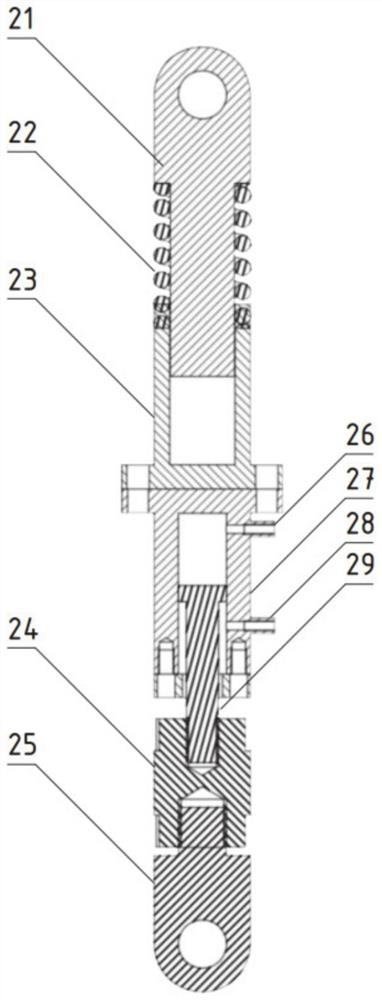
[0035] It mainly includes a hydraulic cylinder, an elastic expansion mechanism and a length adjustment mechanism, wherein one end of the hydraulic cylinder is connected to the elastic expansion mechanism, and the other end is connected to the ground rail fixed block through the length adjustment mechanism;

[0036] The hydraulic cylinder is used as a hydraulic support rod, and the two ends are respectively connected to the elastic telescopic mechanism and the length adjustment structure. The hydraulic support rod applies a given force to the vibration-damping equipment to change the natural frequency of the diesel engine test system. Taking a diesel engine as an example, it can reduce the vibration intensity at each speed of the diesel engine and avoid mechanical resonance under a specific load.

[0037] The elastic telescopic ...

Embodiment 2

[0058] In another typical implementation of the present disclosure, such as Figure 1-Figure 3 As shown, a hydraulic damping system is proposed.

[0059] It includes a plurality of follow-up hydraulic damping devices and control systems as described in Embodiment 1; wherein the hydraulic cylinder is connected to the hydraulic control station;

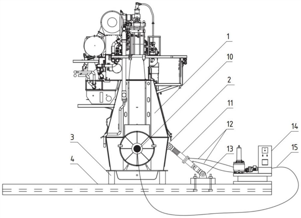
[0060] see figure 1 , two or four hydraulic support rods 11 are symmetrically distributed near the free end and driving end of the low-speed diesel engine 1, and the two ends are connected between the lifting ears 2 of the diesel engine base and the ground rail 4 of the platform; the diesel engine is installed on the on track.

[0061] By applying a given force to the diesel engine 1 through the hydraulic support rod 11 to change the natural frequency of the diesel engine test system, the vibration intensity at each speed of the diesel engine 1 can be reduced, and mechanical resonance under a specific load can be avoided.

[0062] Th...

Embodiment 3

[0068] In yet another exemplary embodiment of the present disclosure, a hydraulic vibration damping method is provided.

[0069] Utilize the hydraulic damping system as disclosed in embodiment 2, comprising the following steps;

[0070] Fix multiple follow-up hydraulic damping devices and the equipment to be damped on the ground rail, and the corresponding multiple hydraulic cylinders are respectively connected to the hydraulic source, and the hydraulic cylinders are connected to the equipment to be damped through elastic telescopic mechanisms;

[0071] The following hydraulic damping device is tensioned by the length adjustment mechanism, so that the spring is at the zero position and the hydraulic cylinder is at the initial position;

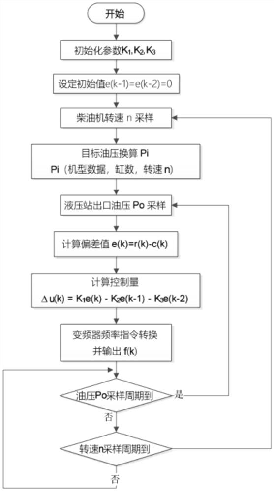
[0072] After the damping equipment is started, drive the hydraulic cylinder to act, change the effect of the follow-up hydraulic damping device on the damping equipment, and adjust the vibration parameters of the damping equipment until the re...


PUM


Abstract

The invention provides a following-type hydraulic damping device, system and method, and relates to the field of damping equipment. The following-type hydraulic damping device comprises a hydraulic cylinder; one end of the hydraulic cylinder is connected with an elastic telescoping mechanism, and the other end of the hydraulic cylinder is connected with a ground rack fixing block through a lengthadjusting mechanism; the elastic telescoping mechanism comprises a telescopic rod which is coaxially in butt joint with the hydraulic cylinder and a spring which is coaxially arranged on the telescopic rod in a sleeving mode; the spring is correspondingly extended or contracted along with the action of the telescopic rod; and the length adjusting mechanism is used for changing the distance betweenthe hydraulic cylinder and the ground rack fixing block. The hydraulic cylinder is matched with the elastic telescoping mechanism so that hydraulic supporting force can be automatically adjusted according to the operation state of to-be-damped equipment, thus the frequency of an offset test system is adjusted, mechanical resonance of the equipment under parts of rotating speeds is reduced, and the equipment is overall protected.

Description

technical field [0001] The present disclosure relates to the field of vibration damping equipment, in particular to a follow-up hydraulic vibration damping device, system and method. Background technique [0002] The statements in this section merely provide background information related to the present disclosure and may not necessarily constitute prior art. [0003] Structural vibration of the low-speed diesel engine body is a common problem in the bench test process of this type of diesel engine. Running the diesel engine for a long time under excessive (exceeding the standard) structural vibration state will cause quality accidents such as component fatigue or even damage. [0004] The vibration of the main body structure of the low-speed diesel engine is directly related to the excitation force of the diesel engine, the speed of the diesel engine under each working condition, and the fixed structure of the diesel engine. Once the model of the diesel engine and the posit...

Claims


Application Information

Patent Timeline
Patent Type & Authority Applications(China)
IPC IPC(8): F16F15/023F16F15/067F16M5/00
CPCF16F15/022F16F15/023F16F15/067F16M5/00
Inventor 张永洪维华赵海辉吕律
Owner 中船发动机有限公司
Why Eureka
Try Eureka