
an automatic exhaust valve

A technology for automatic exhaust valves and exhaust ports, applied to valve details, valve devices, engine components, etc., can solve the problems of poor pressure bearing effect and narrow application range of automatic exhaust valves, and achieve simple structure and good sealing effect , the effect of good application prospects

Active Publication Date: 2022-07-26
中国船舶集团有限公司第七零七研究所九江分部
View PDF5 Cites 0 Cited by
  • Summary
  • Abstract
  • Description
  • Claims
  • Application Information

AI Technical Summary

Problems solved by technology

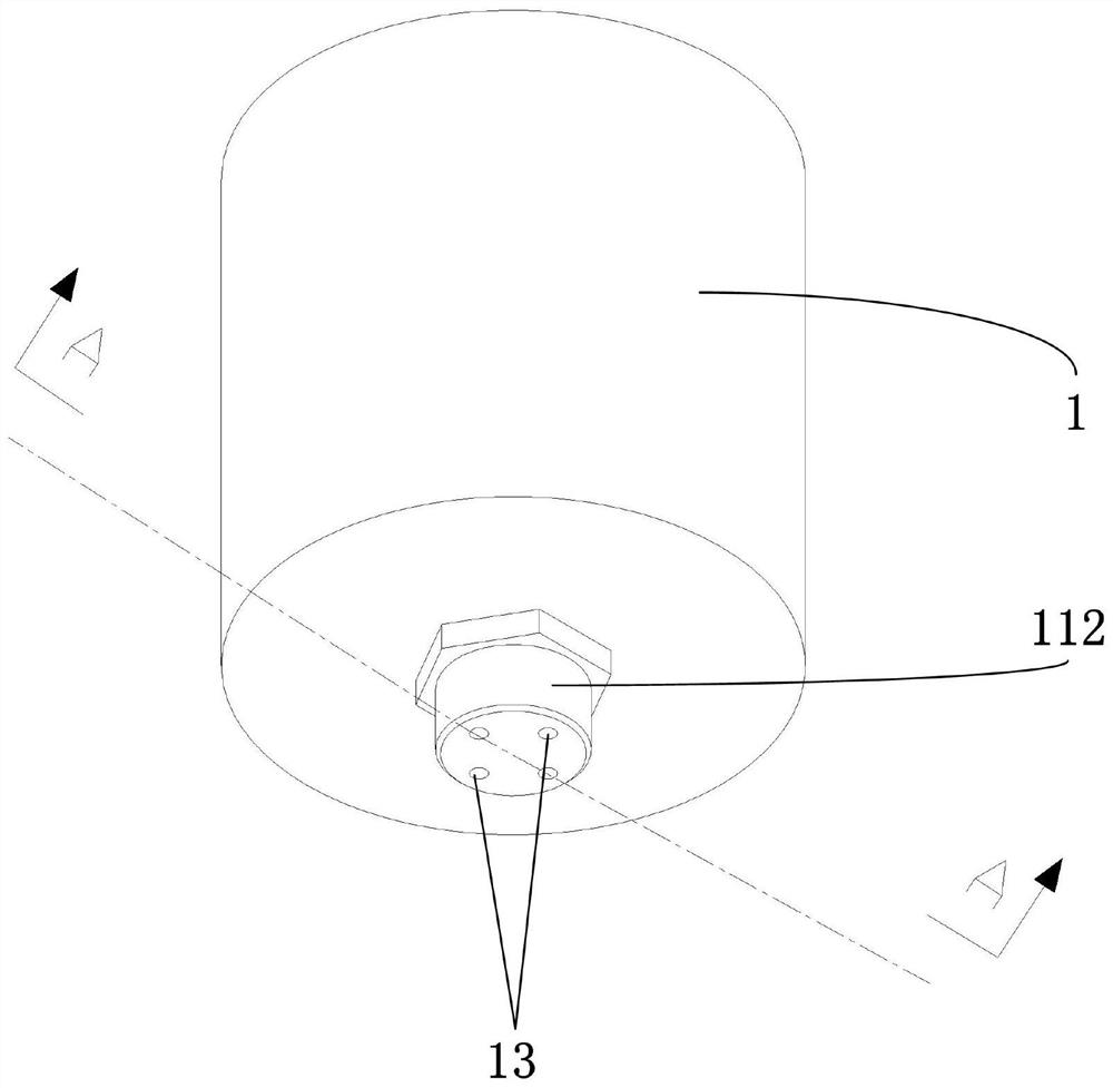
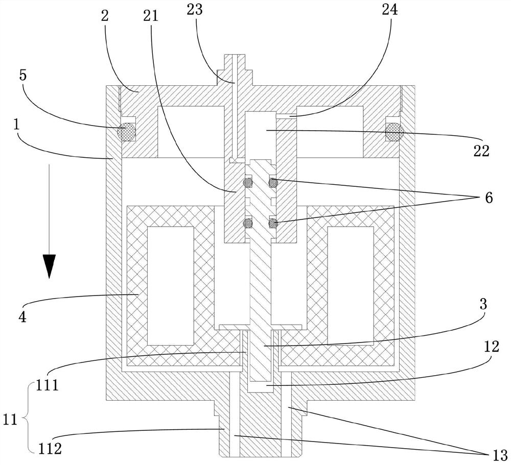
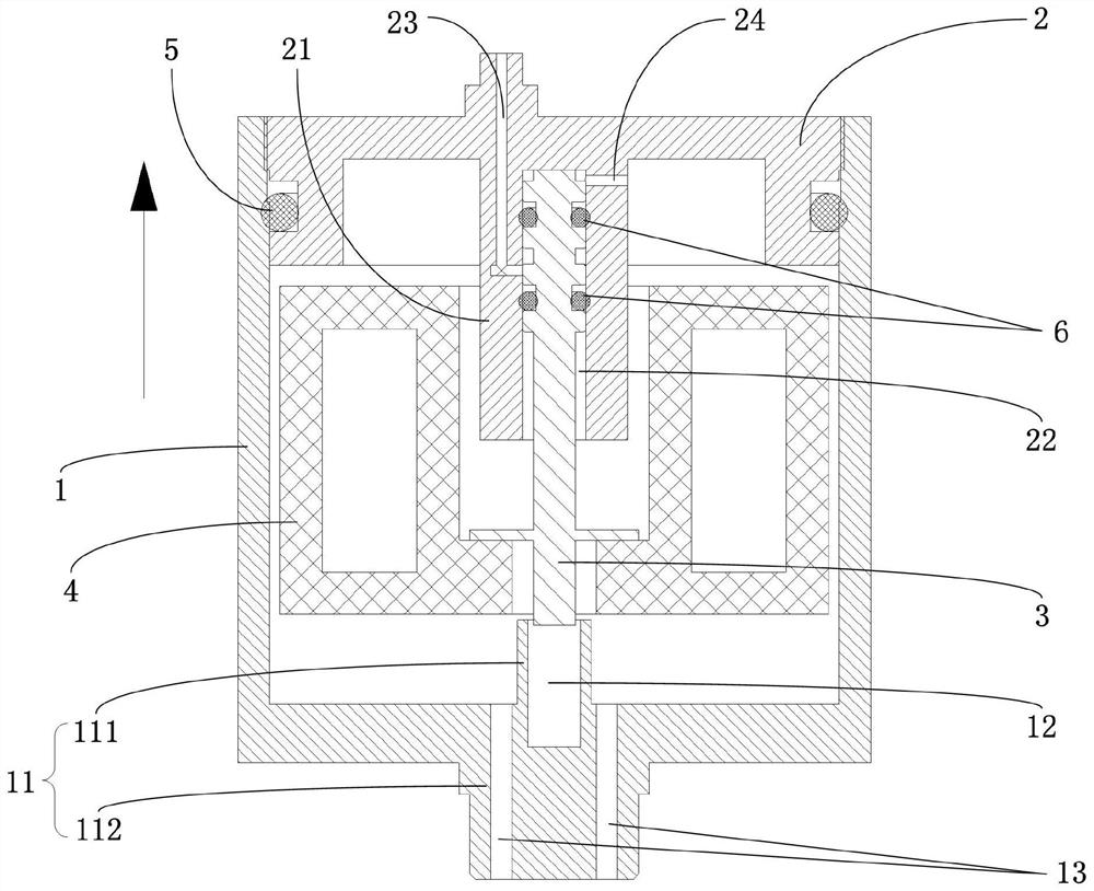
[0004] In view of this, in order to solve the technical problems of poor pressure-bearing effect and narrow application range of the automatic exhaust valve in the prior art, the present invention provides a valve with easy installation, good pressure-bearing performance, good sealing effect and can make the valve core move smoothly. Automatic air vent valve affected by system operating pressure

Method used


Image

  • an automatic exhaust valve
  • an automatic exhaust valve
  • an automatic exhaust valve

Examples


Embodiment Construction

[0036] The following describes in detail the embodiments of the present invention, examples of which are illustrated in the accompanying drawings, wherein the same or similar reference numerals refer to the same or similar elements or elements having the same or similar functions throughout. The embodiments described below with reference to the accompanying drawings are exemplary, and are intended to explain the present invention and should not be construed as limiting the present invention.

[0037] In the description of the present invention, it should be understood that the terms "upper", "lower", "front", "rear", "left", "right", "vertical", "horizontal", "top", The orientation or positional relationship indicated by "bottom", "inner", "outer", etc. is based on the orientation or positional relationship shown in the accompanying drawings, and is only for the convenience of describing the present invention and simplifying the description, rather than indicating or implying t...


PUM


Abstract

The invention discloses an automatic exhaust valve, comprising: a casing, the casing is a hollow structure with an open top, and a first convex column protruding upward is formed in the center of the bottom inner wall of the casing, and an opening is formed on the first convex column The upward first guide groove is also provided with a water inlet hole on the bottom wall of the casing; the cover body is adapted to be installed on the top of the casing, and a second convex column extending downward is formed in the center of the inner wall of the top of the cover body. A second guide groove with a downward opening is formed on the second convex column, and the second guide groove is arranged opposite to the first guide groove; the side wall of the second convex column is also provided with an exhaust port that communicates with the outside and is connected to the shell The exhaust channel communicated with the inner cavity; the valve core, the bottom and the top of the valve core slide in the first guide groove and the second guide groove respectively, and a buoy is also fixed on the side wall of the valve core. The automatic exhaust valve is simple in structure, reasonable in design, convenient in installation, and has good sealing effect.

Description

technical field [0001] The present invention relates to the technical field of exhaust of pipes or water systems, and more particularly to an automatic exhaust valve. Background technique [0002] At present, the existing automatic exhaust valves are only suitable for low-pressure exhaust applications. When it reaches the valve body, due to the action of air pressure, the liquid level in the valve body moves down, and the float drops accordingly. When it falls to the lower limit, the lever system is linked to open the valve port of the exhaust valve to release the gas under pressure, and then the pressure in the valve decreases due to The liquid level moves up, the float rises, and under the action of the spring force, the exhaust port is closed. When this type of exhaust valve is under high system pressure, in order to make the exhaust port open in the normal exhaust state, the gravity of the float must increase a lot, so that the float can overcome the working pressure of...

Claims


Application Information

Patent Timeline
Patent Type & Authority Patents(China)
IPC IPC(8): F16K31/30
CPCF16K31/30
Inventor 胡智华龚涛武永前刘伟萍成慰于少晖刘晓锋张宜华郭星奂
Owner 中国船舶集团有限公司第七零七研究所九江分部
Learn More