
High-efficiency refrigeration industrial fan

An industrial and high-efficiency technology, applied in applications, household heating, household appliances, etc., can solve problems such as general cooling effect, unfavorable resource sustainable development, and inability to realize efficient resource utilization, so as to improve work efficiency and reduce control difficulty Effect

Active Publication Date: 2020-11-06
江苏凯华冷能技术有限公司
View PDF19 Cites 2 Cited by
  • Summary
  • Abstract
  • Description
  • Claims
  • Application Information

AI Technical Summary

Problems solved by technology

[0003] At present, the common industrial fans on the market often need to use a large amount of water when cooling, but most of the other water resources are wasted during the working process except for the part consumed by the fan cooling, resulting in The refrigeration effect is average, and the efficient use of resources cannot be realized, which is not conducive to the sustainable development of resources

Method used


Image

  • High-efficiency refrigeration industrial fan
  • High-efficiency refrigeration industrial fan
  • High-efficiency refrigeration industrial fan

Examples


Embodiment 1

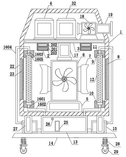
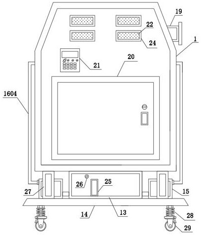
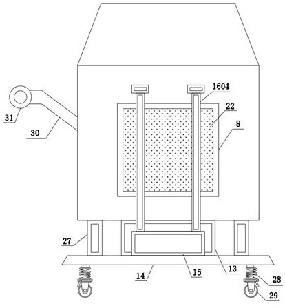
[0036] see Figure 1-5 , a high-efficiency refrigeration industrial fan, comprising a body 1, a sterilizing mechanism 2 is fixedly installed inside the body 1, a partition 3 is fixedly connected to the inner middle end of the body 1, and evaporators are fixedly installed on the left and right sides of the top of the partition 3 4 and condenser 32, the inner bottom of the body 1 is fixedly connected with a receiving seat 5, and the top of the receiving seat 5 is fixedly installed with an exhaust fan 6, and the left and right sides of the exhaust fan 6 are provided with exhaust ports 7, and the left and right sides of the body 1 Both sides are provided with an air inlet 8, the upper ends of the left and right sides of the body 1 are fixedly connected to the upper ends of the air inlets 8, and the lower ends of the left and right sides of the body 1 are fixedly connected to the lower ends of the air inlets 8. 10, the bottom of the upper fixing seat 9 and the top of the lower fixi...


PUM


Abstract

The invention discloses a high-efficiency refrigeration industrial fan, and belongs to the field of fan equipment. The fan comprises a machine body, a sterilization mechanism is fixedly installed inside the machine body, a partition plate is fixedly connected to the middle end inside the machine body, an evaporator and a condenser are fixedly installed on the left side and the right side of the top of the partition plate correspondingly, a bearing seat is fixedly connected to the bottom inside the machine body, an exhaust fan is fixedly installed on the top of the bearing seat, the left side and the right side of the exhaust fan are provided with exhaust ports correspondingly, air inlets are formed in the left side and the right side of the machine body correspondingly, upper fixing seatsare fixedly connected to the left side and the right side inside the machine body and located at the upper ends of the air inlets, lower fixing seats are fixedly connected to the left side and the right side inside the machine body and located at the lower ends of the air inlets, and corresponding positions of the bottoms of the upper fixing seats and the tops of the lower fixing seats are provided with installation grooves. Air is extracted by the exhaust fan through the air inlets, and the air firstly passes through a cooling water curtain when entering the machine body. The cooling water curtain has an initial cooling effect on the air.

Description

technical field [0001] The invention relates to the field of fan equipment, more specifically, to a high-efficiency refrigeration industrial fan. Background technique [0002] Industrial fans refer to fans that are specially used for ventilation in tunnels, underground garages, high-grade civil buildings, metallurgy, factories and mines, and high-temperature smoke exhaust for fire fighting. It is mainly composed of impeller, casing, inlet collector, deflector, motor and other components. The cooling coil, the key component of the high-efficiency cooling fan, is composed of an advanced design of fins and heat exchange tubes. It adopts a new technology of tube expansion, an advanced design structure with variable fin spacing on the air outlet surface, and the heat exchange tubes are arranged in a staggered manner, ensuring The air flow organization is perfect, the air distribution is even and reasonable, and the efficient heat exchange is realized; it is not easy to frost, an...

Claims


Application Information

Patent Timeline
Patent Type & Authority Applications(China)
IPC IPC(8): F24F5/00F24F13/28F24F13/24F24F13/32F24F13/20F24F11/89F04D19/00F04D29/00F04D29/66A61L2/10A61L9/014
CPCA61L2/10A61L9/014F04D19/002F04D29/002F04D29/664F04D29/668F24F5/0007F24F5/0035F24F13/20F24F13/24F24F13/28F24F13/32F24F2013/242F24F2221/125F24F11/89Y02B10/40
Inventor 不公告发明人
Owner 江苏凯华冷能技术有限公司
Learn More