Heat pump drying system

A heat pump drying and water pump technology, applied in drying, heat pump, dryer and other directions, can solve the problems of high condensing temperature, small flow rate, low refrigeration cycle efficiency, etc., and achieve the effect of improving heat transfer coefficient and easy heating

Pending Publication Date: 2020-11-06
张勇
View PDF0 Cites 3 Cited by
  • Summary
  • Abstract
  • Description
  • Claims
  • Application Information

AI Technical Summary

Problems solved by technology

[0002] Conventional dehumidification heat pump drying system, after the treated space passes through the evaporator, in order to increase the dehumidification capacity, the air volume is often reduced, and then through the condenser, the temperature difference of the treated air will be large and the flow rate will be small, making the condensation temperature very high, thus The efficiency of the refrigeration cycle is low

Method used


Image

  • Heat pump drying system
  • Heat pump drying system
  • Heat pump drying system

Examples


Embodiment Construction

[0035] In order to make the purpose, technical solutions and advantages of the embodiments of the present invention more clear, the technical solutions in the embodiments of the present invention will be clearly and completely described below in conjunction with the drawings in the embodiments of the present invention.

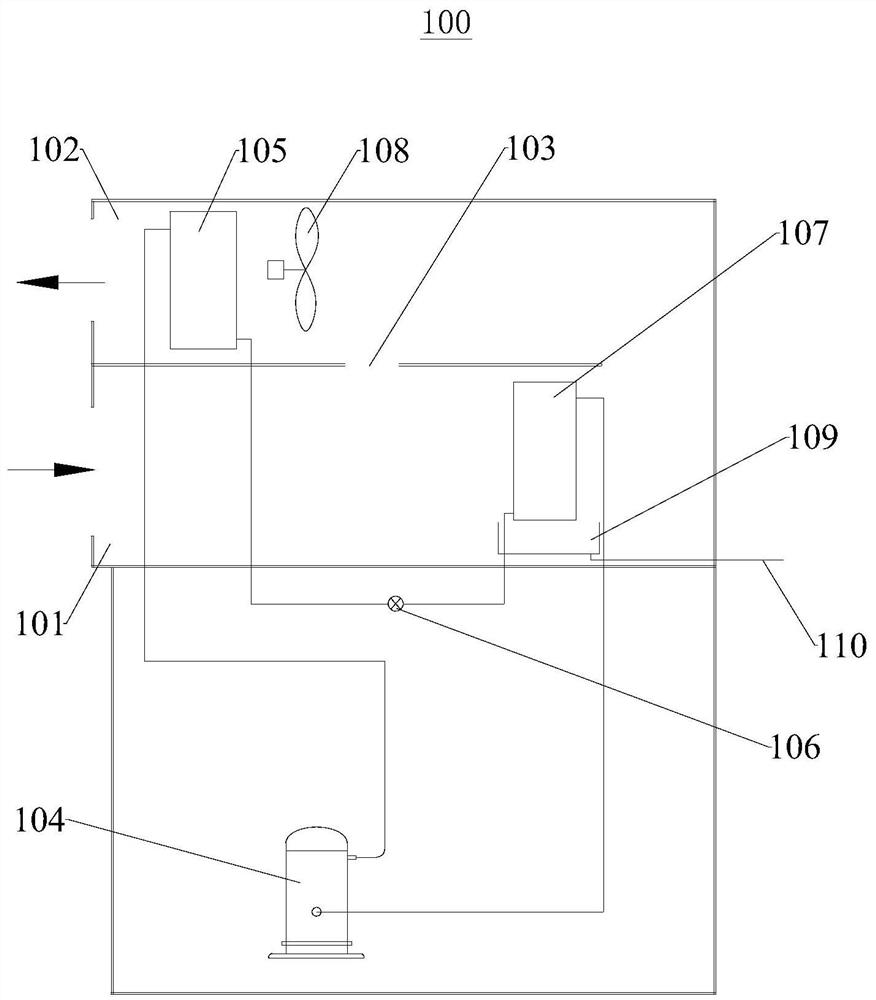
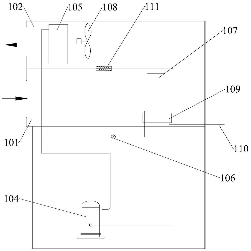
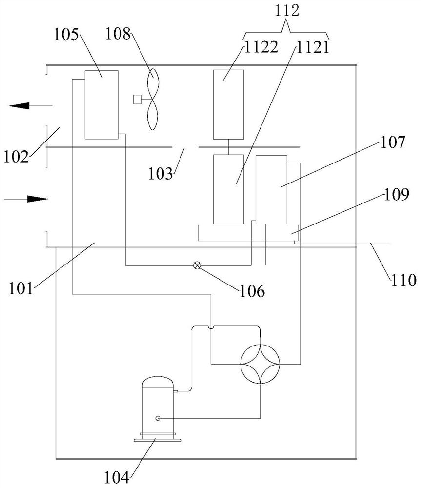
[0036] see figure 1 , the embodiment of the present invention provides a heat pump drying system 100 . The heat pump drying system 100 can be applied to a heat pump drying system to dry crops, medicinal materials, sludge and the like. The embodiment of the present invention can achieve a higher outlet air temperature at a lower condensation temperature, thereby improving the efficiency of the refrigeration cycle and improving the drying treatment efficiency of crops, medicinal materials, sludge, etc.

[0037] In the embodiment of the present invention, the heat pump drying system 100 includes a return air duct 101 , an air supply duct 102 , a bypass air duct ...


PUM


Abstract

The embodiment of the invention provides a heat pump drying system and relates to the field of heat pump drying. The heat pump drying system comprises a wind return wind channel, a wind supply wind channel, a bypass wind channel, a first compressor, a first heat exchanger, a first throttling device, a second heat exchanger and a first fan. An exhausting opening of the first compressor is connectedwith an inlet of the first heat exchanger. An outlet of the first exchanger is connected with one end of the first throttling device. The other end of the first throttling device is connected with aninlet of the second heat exchanger. An outlet of the second heat exchanger is connected with an air sucking opening of the first compressor. The first fan is used for enabling first part air in the wind return wind channel to enter the wind supply wind channel after exchanging heat with the second heat exchanger, and then exchange heat with the first heat exchanger. The first fan is also used forenabling second part air in the wind return wind channel to enter the wind supply wind channel through the bypass wind channel, and exchange heat with the first heat exchanger. According to the heatpump drying system, the higher wind output temperature can be achieved under the circumstance of the lower condensing temperature.

Description

technical field [0001] The invention relates to the field of heat pump drying, in particular to a heat pump drying system. Background technique [0002] Conventional dehumidification heat pump drying system, after the treated space passes through the evaporator, in order to increase the dehumidification capacity, the air volume is often reduced, and then through the condenser, the temperature difference of the treated air will be large and the flow rate will be small, making the condensation temperature very high, thus The efficiency of the refrigeration cycle is low. Contents of the invention [0003] The purpose of the present invention is to provide a heat pump drying system, which can achieve a higher outlet air temperature at a lower condensation temperature, thereby improving the efficiency of the refrigeration cycle. [0004] An embodiment of the present invention provides a heat pump drying system, including a return air duct, an air supply duct, a bypass air duct...

Claims


Application Information

Patent Timeline
Patent Type & Authority Applications(China)
IPC IPC(8): F26B21/00F26B21/02F26B21/08F26B21/10F26B21/12F25B30/02F25B41/06F25D21/14
CPCF25B30/02F25D21/14F26B21/002F26B21/02F26B21/08F26B21/10F26B21/12
Inventor 张勇
Owner 张勇
Why Eureka
Try Eureka